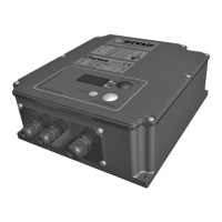
Deutsch SG6 CAN Bus Interface
22
D01596-03
TECHNISCHE DATEN
Ta=25°C wenn nicht anders spezifiziert.
Netzseitig
Beschreibung Symbol Test Kondition Wert und/ oder Bereich
Unit
Netzspannung Vin - 230 ± 10% Veff
Netz-Frequenz f - 50 ÷ 60 Hz
Maximaler Eingangsstrom eff.* If
max
P = P
max
15 Aeff
Inrush Current - Vin=230Veff < 3 A
Leistungsfaktor
cosϕ
P = P
max
0,66 -
Minimale Leistungsaufnahme Pin
min
End of charge < 5 W
Maximale Leistungsaufnahme Pin
max
P = P
max
2,2 kW
* Maximalwert ist Modelabhängig. Die effektive Stromaufnahme entnehmen Sie bitte dem jeweiligen Typenschild.
Batterieseitig
Beschreibung Symbol Test Kondition Wert und/ oder Bereich
Unit
Ausgangsstrom nom. I - See curve ± 5% -
Maximaler Ausgangsstrom I1 Phase 1 See curve ± 5% A
Stromwelligkeit - I = I1 < 5% -
Ruhestrom I
a
Equipment turned off < 0,5 mA
Ausgangsspannung nom. U - See curve ± 0,5% -
konstante Ausgangspannung U1 On the OUT clamps with I = 90% of I1 See curve ± 0,5% V
Spannungsnachführung über Temperatur dU1/dT Phase 2 -5 mV/(°C·cell)
Bereich des Temperatursensors
∆T
- from -20 to +50 °C
Ausgangs Spannungswelligkeit - U = U1 < 1% -
Max. Gleichleistung P
max
U = U1, I = I1 2000 W
Ausgangskapazität C - Depend on the model
(>0,2)
mF
Allgemein
Beschreibung Symbol Test Kondition Wert und/ oder Bereich
Unit
Temperaturbereich (Betrieb)
∆T
- from -20 to +50 °C
Maximale relative Feuchtigkeit RH - 90% -
Schaltfrequenz f
c
- 70 ± 10% kHz
Wirkungsgrad
η
At each operation condition ≥90% -
Abmessungen über alles a×b×c Without connecting cable 276×220×94,2 mm
Gewicht - Without connecting cable 5,5 kg
Schutzklasse - - IP44
-
Grenzwerte
Beschreibung Symbol Test Kondition Wert und/ oder Bereich
Unit
Isolierung - Mains to Battery side 1250 V
AC
Isolierung - Mains side to Earth 1250 V
AC
Isolation - Battery side to Earth 1250 V
AC
Kriechstrom I
L
Supplied equipment < 7 mA
Eingangs-Sicherung F1 Inside the equipment 20 A
Ausgangs-Sicherung F5 To be externally mounted
about 1,2×I1
A
Min. Anlaufspannung (Batterie-Erkennung) - Equipment turn on See curve V/cell
Maxim. Ausgangsspannung Um Phase 3 (IUIa - IUIUo) See curve V
Verpolung - At the connection to the Battery Protection provided by
external fuse
-
Temperaturbegrenzung Halbleiter
(Temperatur Alarm)
- 100 °C
Sicherheitsnormen - EN60335-1, EN60335-2-29 - -
EMV Konformität - EN55011 (conducted EMC) - -
Dieses Gerät entspricht der Niederspannungsrichtlinie 2006/95/CE.