SG6 CAN Bus Interface English
D01596-03 9
Warning
• This user manual must be intended as part of the product.
• Do not make any modification to the product.
• Do not use for any different purposes.
• In order to guarantee the suitable protection against accidental contact to live parts, a proper connector must be installed on the output
Cables
• An overcurrent protection device must be installed at the unit output, see electric feature section for its ratings.
Visualization
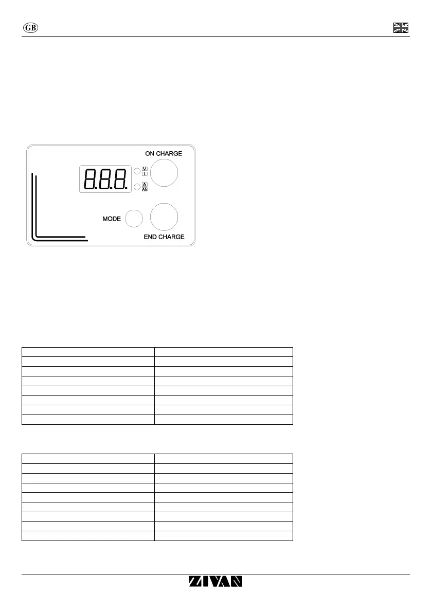
Digital instrument (display version)
From the starting the digital instrument will display the string of the following parameters:
• BATTERY VOLTAGE (two-tone red upper led).
• CURRENT provided by the charger (two-tone red lower led).
• TIME in hours lacking to the end of charge (two-tone green upper led).
• Ah supplied (two-tone green lower led).
By pressing the MODE button, the parameters’ sequence is blocked and it will be kept the last value displayed. By pressing again on the
MODE button the sequence of parameters restarts.
BIG LED indicators (display version)
Colour Description
Red Constant or Max current phase (IUIa).
Blinking red (4s ON – 1s OFF) Voltage control phase (IUIa).
Red and blinking green (4s ON – 1s OFF) Overcharging phase (IUIa).
Red and green alternated Wait phase (for equalization) (IUIa).
Green End charge
Blinking green (4s ON – 1s OFF) Equalization pulse and floating
Green and red blinking together Connection with CanConsolle or S/S HW-SW.
BI-COLOR LED indicator (version without display)
Colour Description
Red Constant or Max current phase (IUIa).
Blinking red (4s ON – 1s OFF) Voltage control phase (IUIa).
Orange Overcharging phase (IUIa).
Blinking Orange (4s ON – 1s OFF) Wait phase (for equalization) (IUIa).
Blinking Orange (1s ON – 1s OFF) Allarm.
Green End charge
Blinking green (4s ON – 1s OFF) Equalization pulse and floating
Green red alternated Conection with CanConsolle or S/S HW-SW.