11
12
RS485 Connection
PC Connection
Important Notes:
2. RS485 communication wires should be connected in a bus cascade instead
of a star form, to achieve a better shielding eect by reducing signal reec-
tion during communications.
3. Adjust the communication speed as needed. The signal quality vary depend-
ing on wiring conditions, and it maybe necessary to lower the baudrates.
4. The GND Signal may be omitted if and only if the GND potential dierence
is less than ±5V
Do not use
PIN DESCRIPTION WIRE
1
WD0 Green
2
WD1 White
3 GND Black
4
RXD Gray
5
6 GND Black
7
8
485B Yellow
485A Blue
TXD Purple
1
8
1. RS485 communication wires should be a shielded and twisted pair cable.
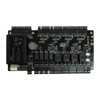
RLED
RJ45-1
COM1
+12V
BUT
BELL+
BELL-
RJ45-3
GLED
AL-
IWD0
NO1
GND
RJ45-2
IWD1
NC1
GND
SEN
RJ45-6
BEEP
AL+
Ethernet
Alarm
Wiegand In
Output
Wiegand Output
RS485
Lock
Bell
Power Out
Sensor
Button
RXD
GND
WD1
TXD
485A
GND
485B
WD0
+12V
GND
GND
AUX
Auxiliary In
RS232
Power In
}
}
}
}
}
}
}
}
}
}
}
}
}
}
RS485
#1 ProCapture #2 ProCapture #63 ProCapture
RS485 B
RS485 A
GND
Incorrect RS 485 connections
485A
485B
GND
485A
485B
GND
PC
485A
485B
GND
PC
RS485
#1 ProCapture #2 ProCapture #63 ProCapture
RS485 B
RS485 A
GND
x
485A
485B
GND
PC
485A
485B
GND
PC
485A
485B
GND
PC
#1 ProCapture #2 ProCapture #63 ProCapture
RS485 B
RS485 A
GND
RS485
x
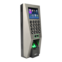
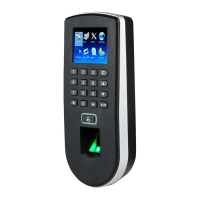
2.4 Inch TFT Time Attendance &Access Control Terminal INSTALLATION GUIDE 2.4 Inch TFT Time Attendance & Access Control Terminal INSTALLATION GUIDE
 Loading...