EasyManua.ls Logo

ZKTeco F19 User Manual

ZKTeco F19
2 pages
To Next Page IconTo Next Page
Page #1 background imageLoading...
Page #1 background image
(1) Paste the mounting template on the
wall. Drill the holes according to
the marks on the template (holes
Version: 1.0 Date: June, 2012
(2) Remove the screw on the
(3) Take away the back plate.
(5) Place the unit onto the mounting bracket,
plate on the wall according to
(4) Fix the rubber pad and the back
RS485
TCP/IP
Lock
Sensor
Alarm
RS232/RS485 Converter
NC LOCK
-
+
DC12V
+
NC LOCK
+
-
NO LOCK
-
-
FR 107
+
-
+12V
+12V
+12V
+12V
GND
GND
GND
GND
GND
GND
GND
GND
GND
SEN
SEN
SEN
SEN
SEN
BUT
BUT
BUT
BUT
BUT
BELL+
BELL+
BELL+
BELL+
BELL+
BELL-
BELL-
BELL-
BELL-
BELL-
NO LOCK
-
+
DC12V
+
-
+
-
FR 107
FR 107
-
+
DC12V
+
-
-
+
DC Power
-
+
DC12V
-
+
DC Power
+
-
FR 107
+
DC12V
-
+
GND
+12V
Exit Button
Reader
Bell
Door Bell
%
%
-
+
Alarm
Alarm Power
Exit Button
Door Sensor
for screws and wiring).
bottom of device.
Access Control System Function
(1) If a registered user verified, the device will send a signal
to unlock the door.
(3) If the d llegal , the device will signal the alarm. evice is i ly removed
(4) is External card reader supported.
(5) is External exit button supported.
(7) Supports , communication RS485 TCP/IP to be able to connect with
PC. One PC can manage multiple devices.
(6) External door bell is supported.
①: ‘I’: device output current, ‘ ’: lock voltage, ’: lock currentULOCK ILOCK
(1) The system supports NO LOCK and NC LOCK. For example the NO LOCK (normally open at
(2) When the Electrical Lock is connected to the Access control System, you need to connect one FR107
diode parallel with the connection (shipped in the package) in to prevent the self-inductance EMF
power on) is connected with ‘ NO’ and COM terminals, and the NC LOCK(normally close at power
3.Lock Connection
WARNING: Do Not operate with Power connected.
(1) Share power with the lock:
ULOCK=12V, I-ILOCK>1A
And the distance between the lock
Device shares power with the lock:
Does not shares power with the lock:
A. =12V I- 1A;ULOCK ILOCK
B 12V; . ULOCK
C. The distance between the lock and
Alarm Voltage output DC 12V
4. Other Connections
5. Power Connection
The device working voltage DC 12V, electric current
500mA (50mA standby). Positive is connected with
‘+12V’, negative is connected with ’GND’.
(2) Does not share power with the lock:
2. Structure and Function
Installation Guide
1. Equipment Installation
NC1
NC1
NC1
NC1
NC1
NO1
NO1
NO1
NO1
NO1
COM1
COM1
COM1
COM1
COM1
NO2
NO2
NO2
NO2
NO2
COM2
COM2
COM2
COM2
COM2
and tighten the screw at the bottom of the unit.
(2) The door sensor will detect the ON-OFF state. If the door
is unexpectedly opened or improperly closed, the alarm signal
(digital value) will be triggered.
the mounting paper.
on) is connected with ‘NC’and ‘COM’ terminals.
feedback the system. NB: Do not reverse the polarities!
and the device is equal or less
the device is more than 10 meters.
than 10 meters.
* All rights .reserved
1 2 3
4
5
6
7 8 9
0
C
M/OK
Exit
Exit
+Power-
(Do not reverse the polarities)
Wiring H ole
Instru ction f or the Mo untin g Paper
Stick thi s mount ing pap er to the w all or
door fram e. Dril l the hol es acco rding t o
the mount ing pap er.
Fixing H ole
10
11
12
13
14
15
16
Mou nting P aper
Fixing H ole
Fixing H ole Fixing H ole
Question and Answer IconNeed help?

Do you have a question about the ZKTeco F19 and is the answer not in the manual?

ZKTeco F19 Specifications

General IconGeneral
ModelF19
Fingerprint Capacity3000
Max User Capacity3000
Transaction Capacity100, 000
Access Control Interface3rd Party Electric Lock, Door Sensor, Exit Button, Alarm
Operating Humidity20% to 80%
CommunicationTCP/IP, RS485
DisplayTFT LCD
Power SupplyDC 12V
Operating VoltageDC 12V
Supported ReadersFingerprint
Door Lock Control Output1
Door Sensor Input1
Exit Button Input1
Alarm Output1
TypeFingerprint Access Controller

Summary

Equipment Installation

Mounting Template and Back Plate

Steps for preparing the wall and attaching the device's back plate and rubber pad.

Final Device Mounting

Securing the device unit onto the mounting bracket and tightening the screw.

Structure and Function

Door Unlock and Sensor Functions

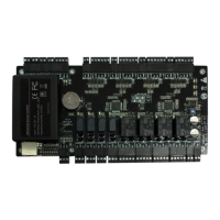
Device signals door unlock and detects door state for alarm triggers.

Tamper and External Device Support

Alarm for illegal removal, support for external reader, exit button, and door bell.

Communication Interface

Supports RS485 and TCP/IP communication for PC connectivity.

Lock Connection

Shared Power Wiring

Wiring configuration for sharing power with the lock, specifying voltage and distance limits.

Independent Power Wiring

Wiring configurations for locks with different voltage or distance requirements.

Other Connections

External Device Connections

Diagrams and labels for connecting external exit buttons, door bells, and door sensors.

Power Connection

Device Power Specifications

Specifies DC 12V voltage and 500mA current for device operation.

Alarm Output Voltage

Details the DC 12V output voltage for alarm signals.

Wiegand Output

Standard Wiegand Support

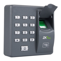
Device supports standard Wiegand 26-bit output for access control devices.

Wiegand Input

Slave Card Reader Connection

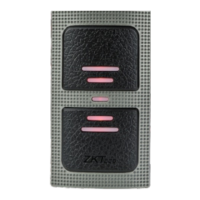
Enables connection to a slave card reader for dual-side door control.

Wiegand Signal Best Practices

Guidelines for distance, grounding, and signal integrity for Wiegand connections.

Other Functions

Manual Reset Procedure

Instructions on how to restart the device using the reset button.

Restore Factory Settings

Procedure to reset device settings using the tamper switch.

Communication

RS485 Communication Setup

Details on using RS485 wire, converter, and bus-type wiring for PC communication.

TCP/IP Connection Options

Explains direct crossover cable and LAN/WAN switch connections for TCP/IP.

Cautions

Installation and Operation Warnings

Important safety and operational advice for installation and use, including power connection and wire handling.

Power Supply Recommendation

Recommendation for using a DC 12V/3A power supply for the device.

Wiring and Grounding Guidelines

Advice on wire exposure, grounding, and cable type for long-distance installations.
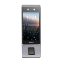
Related product manuals