DATA1
DATA0
GND
+12V
GLED
RLED
BEEP
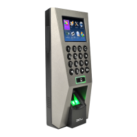
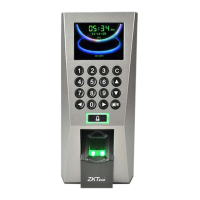
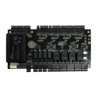
Access Control Panel
IP Address:192.168.1.201
Subnet Mask:255.255.255.0
IP Address:192.168.1.124
Subnet Mask:255.255.255.0
Side View Back View
Tamper Switch
Reset Button
About the terminals definition, please refers
to the right table.
RXD Pin3-Txd
TXD Pin2-Rxd
GND Pin5-Gnd
485+ RS485+
485- RS485-
10. Cautions
6. Wiegand Output
The device supports standard Wiegand,
26-bit output, so you can connect it with
7. Wiegand Input
connection to a slave card reader. Device are control
The device has a Wiegand input port, which enables the
(In case of long distance installation, use the Wiegand Signal Extender to minimise interference).
(2) To keep a balanced and stable Wiegand signal, connect the device, access control lock and card reader
(1) Do not exceed distance between the Device and Access Control Lock OR Card reader. 90m(meters)
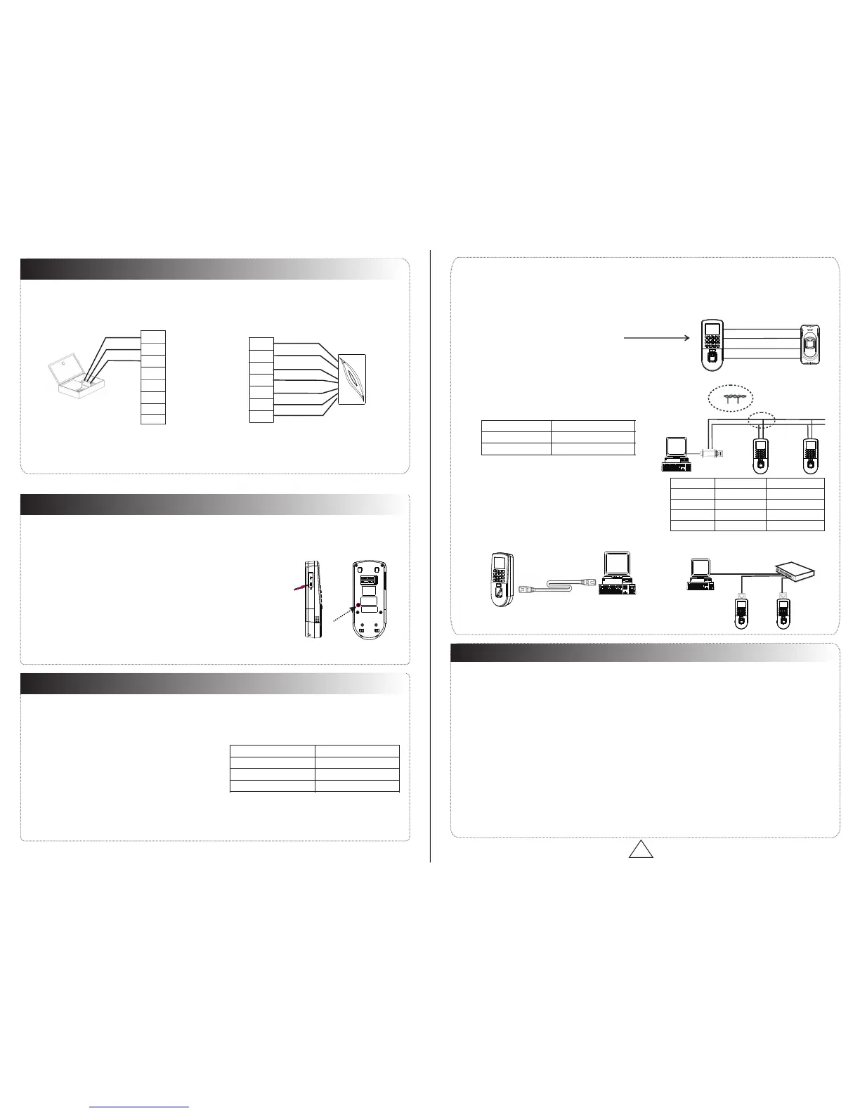
There are three modes that the PC software could communicate and exchange information with the device:
RS485 and TCP/IP, and supports remote control.
9. Communication
8.Other Functions
(1) Manual Reset:
(2) Restore Factory Settings:
(A) Crossover cable: The device and PC
(B) Straight cable: The device and PC connected
2. TCP/IP Mode:
1. RS485 Mode:
Operation: 30-60 seconds after the tamper alarm has sounded,
other restart it.abnormality, you can use ‘Reset’ function to
If the device does not work properly because of misoperation or
button hole with than 2mm).a sharp tool (the tip diameter is less
Operation: Remove the black rubber cap, then stick the Reset
You can use the tamper switch to restore factory settings, such as
device number, system password, IP address, RS485 address, etc.
press the tamper switch three times.
Terminals PC Serial Ports
Terminals PC Serial Ports
Terminals Wire Name Color
on the same ‘GND’ (ground) port.
devices on both sides of the door to control the access
Please use specified RS485 wire, RS485 active
converter and bus-type wiring.
Terminals:
to LAN/WAN through switch/Lan switch.
connected directly.
various access control devices.
485+
485-
485+ 485-
RS485 Bus
485+ 485- 485+ 485-
RS485
Converter
RJ45-1 TX+ White-orange
RJ45-3 RX+ White-green
RJ45-6 RX- Green
DATA0
GND
DATA1
and electric lock.
The user data won't be cleared.
Two ways for TCP/IP connection:
Switch
PC
…
RJ45- TX Orange2 -
Communications of PC:
Re
ad
e
r
Y
e
l
low
485-
4
8
5
+
P
ur
p
l
e
A
c
c
e
s
s Con
tr
o
l De
vi
ce
Re
d
P
o
w
e
r-
P
o
wer
+
Blac
k
Diagram of RS485Reader Function (Right)
485+
485-
TXD
RXD
GND
GND
WD0
WD1
IWD1
+12V
BEEP
GLED
RLED
IWD0
GND
1 2 3
4
5
6
7 8 9
0
C
M/OK
1 2 3
4
5
6
7 8 9
0
C
M/OK
1 2 3
4
5
6
7 8 9
0
C
M/OK
1 2 3
4
5
6
7 8 9
0
C
M/OK
1 2 3
4
5
6
7 8 9
0
C
M/OK
* All rights .reserved
!
WARNING: Do Not operate with Power connected.
(1) Connect the power cable after al the wiring has been completed. If the device is working
abnormally, please shut down the device, and make necessary checks. Please note that any
"HOT SWOP" of wiring on the device may damage the device, and the warranty does not
cover damage caused by improper operations.
(2) We recommend use the DC 12V/3A power supply. Please contact our technical staff for details.
(3) Please read the terminal and wiring description and diagrams carefully before commencing
with installations. Any damage to the device caused by improper operations, will not be covered
under warranty.
(4) Keep the exposed part of wire less than 5mm, to avoid unexpected connection.
(5) Please connect the 'GND' when starting installations, especially in an environment where static
electricity is very high.
(6) Do not change the cable type in case of a long distance installations.
Please use specified RS485 wire, RS232/485 active
converter, which consists of bus-type wiring.
you need to parallel a terminal resistance on the receiving
If the communication wire is longer than 100maters,
end, and resistance value is about 120 ohm.
Equipment supports 485reader function, can be through the 485communication connected to
FR1200 reader; meanwhile, it can act as Master-slaver which device for master, FR1200 reader
for slaver, achieve 485 Anti-passback functions. If select “485reader function” , so device can
not connect with PC through 485 communications.
RS485Reader:

 Loading...