(1) Post the mounting template on the
wall.Drill the holes according to
the marks on the template (holes
Version: V1.0 Date: April, 2011
(2) Remove the screws on the bottom
(3) Take away the back plate.
(5) Tighten the screws on the bottom,
plate on the wall according to the
(4) Fix the plastic pad and the back
RS485
TCP/IP
Lock
Sensor
①
③
Alarm
RS485 Converter
②
NC LOCK
-
+
DC12V
+
NC LOCK
+
-
NO LOCK
-
-
FR 107
+
-
FR 107
+12V
+12V
+12V
+12V
GND
GND
GND
GND
GND
GND
GND
GND
GND
SEN
SEN
SEN
SEN
SEN
BUT
BUT
BUT
BUT
BUT
BELL+
BELL+
BELL+
BELL+
BELL+
BELL-
BELL-
BELL-
BELL-
BELL-
NO LOCK
-
+
DC12V
+
-
+
-
FR 107
-
+
DC12V
+
-
-
+
DC power
-
+
DC12V
-
+
DC power
+
-
FR 107
+
DC12V
-
+
GND
+12V
Exit Button
⑤
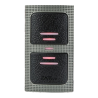
External Reader
④
Door Bell
Door Bell
%
%
BUT TON
EXI T
EXI T
BUT TON
⑦
⑥
-
+
Alarm
Alarm Power
Exit Button
Door Sensor
for screws and wiring).
of device.
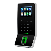
Access Control System Function
(1) If a registered user verified, the device will export the signal
to unlock the door.
(3) If only the d llegal removed, the device will evice being i ly
(4) is External card reader supported.
(5) is it is External exit button supported, convenient to open the
(2) Door sensor will detect the on-off state If the door is unexpected
opened or improperly closed, the alarm signal (digital value) will be
triggered.
export alarm signal.
door inside.
(7) Supports , modes with RS485 TCP/IP to connect PC. One PC can
manage multiple devices.
(6) External door bell is supported.
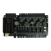
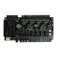
①: ‘‘I’: device output current, ‘ ’: lock voltage, ’: lock currentULOCK ILOCK
(1) The system supports NO LOCK and NC LOCK. For example the NO LOCK (normally open at power on) is connected
with ’NO’ and terminals, ’COM’ and ’COM’ terminalsand the NC LOCK is connected with ‘NC’ .
(equipped in the package) to prevent the self-inductance EMF affect the system, do not reverse the polarities.
3.Lock Connection
!
Warning: No operating with power on
(1) Share power with the lock:
A. ULOCK=12V, I-ILOCK>1A…… ①
B. The lock is near to the device.
Device share power with the lock:
Device does not share power with the lock:
A. =12V I- ≤1A;ULOCK ILOCK
B ≠12V; . ULOCK
C. The lock is far apart from the device.
Voltage output ≤ DC 12V for Alarm
4. Other Parts Connection:
5. Power Connection:
Input DC 12V, 500mA (50mA standby)
Positive is connected with ‘+12V’, negative is connected
with ’GND’ (do not reverse the polarities).
(2) Does not share power with the lock:
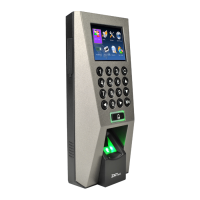
2. Structure and Function
F17 Installation Guide
1. Equipment Installation
(2) When the Electrical Lock is connected to the Access Control System, you need to parallel one FR107 diode
NC1
NC1
NC1
NC1
NC1
NO1
NO1
NO1
NO1
NO1
COM1
COM1
COM1
COM1
COM1
NO2
NO2
NO2
NO2
NO2
COM2
COM2
COM2
COM2
COM2
fix the device to the back plate.
Wir ing Hol e
Inst ruct ion for th e Moun ting Pap er
Befo re the d evice is f aste ned, ple ase
stic k the pa per to the p lace w here you
want t o inst all it, th en mak e holes an d
lay ca bles a ccordi ng to th e mounti ng
pape r.
F17 Mounting Paper
(only for yo ur re fer ence)
Fix ing Hol e
Fix ing Hol e
Fix ing Hol e
10
11
12
13
mounting paper.