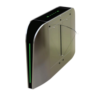
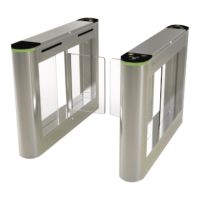
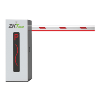
This document describes the FBL200/300 Flap Barrier, an intelligent channel management equipment designed for civilized and orderly personnel traffic while preventing unauthorized entry and exit. The system integrates mechanical, electronic, and microprocessor control with various reading and writing technologies. It also incorporates reliable safety protection devices, real-time alarm systems, and a direction indicating interface for comprehensive channel control and management.
The equipment's appearance is characterized by its stainless steel plate construction, which ensures durability and rust-proof properties. It features standard electrical interfaces, allowing for easy integration with various card readers such as bar code, ID, and IC card readers. The system is also designed to meet fire protection requirements, ensuring unobstructed passages for timely evacuation during emergencies.
Important Technical Specifications:
- Power Supply Voltage: AC220±10% V, 50HZ
- Drive Motor: DC motor 24V/40W
- Working Environment Temperature: -15°C to 60°C
- Relative Humidity: ≤90%, non-condensing
- Input Interface: 12V level signal or pulse width > 100ms
- Communication Interface: RS232 communication, relay opening signal
- Channel Width: Wing gate 580mm, wing plate 260mm
- Passing Speed: 30 people/minute (normally open mode), 20 people/minute (normally closed mode)
- Gate Opening and Closing Time: 0.8 seconds for wing gate
Usage Features:
The FBL200/300 Flap Barrier offers several features to enhance security and user experience:
- Alarm Prompt for Illegal Entry: The system issues an alarm prompt if an illegal entry attempt is detected.
- Anti-Shock Function: The telescopic baffle automatically locks if an opening signal is not received, preventing unauthorized forcing.
- Infrared/Mechanical Dual Anti-Pinch Function: During baffle resetting, the motor automatically stops within a specified time if an obstruction is detected. The force applied is minimal, and an alarm signal is simultaneously issued, ensuring pedestrian safety.
- Automatic Reset Function: If a pedestrian reads a valid card but does not pass within a specified time, the system automatically cancels their permission to pass for that instance.
- Unified Standard External Electrical Interface: This allows for connection to various card readers and remote control/management via a computer.
- Fire-Fighting Function: Upon receiving a fire-fighting signal, the gate automatically opens to facilitate evacuation. Additionally, the gate is equipped with a battery, ensuring it automatically opens during a power outage.
- Smooth and Low-Noise Operation: The entire system is designed for quiet and efficient performance.
System Working Principle:
- Power-On: The system enters a working state 3 seconds after power-on.
- Card Reading: When a valid card is read, the buzzer emits a sound, confirming successful card reading. The system processes the card information and sends an approval signal to the main control board.
- Gate Opening: The main control board, after processing signals from the card reader and infrared sensor, sends control signals to the direction indicator and motor. The direction indicator displays a green arrow, and the gate opens, allowing passage.
- Passage Monitoring: As a pedestrian passes, the infrared sensor continuously monitors their progress, sending signals to the main control board until the passage is complete.
- Illegal Entry Handling: If a pedestrian attempts to enter without reading a card or with an invalid card, the system prohibits passage and issues a voice alarm (e.g., "illegal intrusion, please swipe the card"). The alarm persists until the pedestrian exits the passage, requiring a valid card swipe for subsequent entry.
Equipment Installation and Commissioning:
Installation involves several steps to ensure proper functionality:
- Tool Preparation: Gather necessary tools and verify accessories against the packing list.
- System Planning: Clarify the system composition and working methods, then plan the overall installation.
- Foundation Preparation: Prepare the foundation surface and arrange the equipment.
- Hole Drilling: Drill holes and embed M12 anchor bolts or expansion bolts.
- Cable Burial: Thread high-current and weak-current cables through 3/4" PVC pipes and bury them in the designated positions with cement.
- Chassis Alignment: Move each chassis to its installation position, aligning anchor bolt positions.
- System Verification: Check the system composition and working method for correctness before proceeding.
- Initial Fastening: Open the cabinet door, select one device as a reference (preferably the middle one), align bolt holes with anchor bolts, and pre-tighten nuts. Repeat for adjacent chassis.
- Wiring: Refer to the wiring diagram to connect power lines, control lines, and the system protection ground line.
- Final Tightening: After state inspection and function debugging are qualified, tighten the anchor nuts.
Installation Warnings:
- Buried PVC line pipes should be deeper than 60mm, with exposed ground height greater than 50mm, and the outlet bent back to prevent water ingress.
- Left and right gates of each channel must be aligned during installation.
- Connect the system protection ground wire reliably.
- For outdoor use, build a cement platform (100-200mm high) to prevent moisture and add sun/rain-proof facilities.
- The equipment should only be put into normal use after state inspection and function debugging are qualified.
Equipment Function Debugging:
Debugging can commence after the equipment status is checked normally.
- Preparation: Verify mains wiring according to the diagram, ensuring all power and other wiring is correct. Power on and debug after confirmation. The protective ground must be reliably connected.
- Parameter Setting: The control board's LCD screen displays the default state (working model, pass counts). Five operation buttons are available:
- Menu: Enters menu settings.
- Up/Down: Navigates menu items.
- OK: Enters a setting item or confirms a modified value.
- Cancel: Returns to the previous menu or cancels the current operation.
- Menu Operation: Press "Menu" to enter the password interface (default: up, down, down). Enter the 6-bit password and press "OK" to access the menu. Use "Up/Down" to select features, then "OK" to change values.
- Example: To change the gate's working mode, navigate to "gate working mode," press "OK" (shows current mode), press "OK" again to enter modification, use "Up/Down" to select the desired method, press "OK" to confirm, and "Cancel" to exit. The system automatically exits after 15 seconds if no key is pressed.
- In and Out Direction Configuration: Sets the left and right sides for entrance or exit.
- Entry and Exit Pass Configuration: Determines if both sides of the gate allow passage.
- How the Gate Works: Sets the opening mode (e.g., open for infrared, swipe to open).
- Inlet Memory Function Configuration: Configures whether the system remembers multiple card swipes before a person passes. "Prohibited" means only the first swipe is effective until that person passes. "Allowed" means multiple consecutive swipes can be remembered, allowing multiple individuals to pass.
- Length of Time Entrance and Exit is Open: Sets the duration the gate remains open if no one passes (default: 3 seconds).
- Counter Reset: Empties and recounts inlet/exit passes.
- Device Number: Control board device number (generally not used for settings).
- Device Information: Displays basic control board information (type, model).
- Gate Type: Sets the gate type (wing gate, swing gate, open the gate; default: Wing Gate).
- System Initialization: Resets control board parameters to factory settings.
- Left Pass Voice: Sets the voice prompt for passing from the left (e.g., "Welcome").
- Right Pass Voice: Sets the voice prompt for passing from the right (e.g., "a safe journey").
- Test Voice: Automatically plays all internal voice prompts and exits.
- Motor Speed: Sets motor running speed (smaller value = slower speed).
- Default: (No description provided in the manual, likely a placeholder or general setting).
- Motor Maximum Running Time: Sets the longest time the motor can run continuously (default: 10s) to prevent idling in case of external detection failure or no signal.
- Allow Infrared Overlap Time: Allows simultaneous blocking of 2 infrared beams to prevent false alarms due to short spacing between sensors (e.g., left infrared and anti-clamp close).
- Delayed Closing Time: Sets the delay (in seconds) before the gate closes after a person passes (default: 0s for immediate closing).
- Default: (No description provided in the manual, likely a placeholder or general setting).
- Gate Test: Repeatedly opens the gate for stability and aging tests (not for user use).
- Power-Off Opening Setting: (No further description provided).
- Wing Gate Infrared Settings:
- 1 over the last pair of infrared gate
- 2 through the anti-clamp gate
- Illegal Break-In Operation:
- Motor Brake Setting:
- 1 Close brake
- 2 Open brake
- Gate Machine Often Open Set the Opening Signal is Greater Than the Change of Value Often Open: (Description unclear, likely relates to continuous open mode based on signal strength).
- Swipe When the Alarm is Set When the Alarm is Allowed to Swipe or Do Not Allow the Swipe: (Description unclear, likely relates to alarm behavior during card swipe).
- Developer Options: (No further description provided).
Notes for Debugging:
- Do not add peripheral devices without permission.
- If debugging results are inconsistent with described functions, refer to the common faults and troubleshooting section.
Equipment Operation Instructions:
- Pre-Use Debugging: The equipment must pass function debugging before normal use.
- Channel Safety: Strictly forbidden to stand in the channel when the equipment is powered on.
- Direction Indicator: Pedestrians are not allowed to enter if the direction indicator is not green after reading a card.
- Passage Flow: Do not stay in the middle of the passage for extended periods.
- Crowding: Avoid crowding when passing; maintain a safe distance between individuals.
- Card Reading Requirement: Strictly forbidden to pass without reading a card.
- Instruction Marking: It is recommended to conspicuously mark pass instructions near the equipment to guide users safely.
- Equipment Management: When not in use, the equipment must be properly managed; strictly prohibit knocking or shaking.
- Gate Closure: When the gate is closed, strictly forbidden to push, pull, or hit it forcefully.
Operation Warnings:
- Do not use the machine during thunder and lightning to prevent damage.
- Ensure the system's protected ground is reliably connected to prevent personal injury.
Common Faults and Analysis:
- Proximity Switch: Used for position control (wing brake). It has 3 lines: brown (+12V), blue (GND), and signal output. Output is +12V when sensing a magnet/metal object (2-4mm distance), otherwise 0V.
- Motor: DC24V motor with a load current of approximately 300mA, less than 1.2A.
- Cylindrical Photoelectric Switch: Used for alarm and anti-pinch detection. Composed of a transmitter and receiver.
- Transmitter: 2-wire power input (brown +12V, blue GND), power indicator normally on.
- Receiver: 2-wire power input (brown +12V, blue GND), 1-line signal output (black). When the area is accessible (isolated), it outputs +12V and the indicator lights up, otherwise 0V.
- Cylindrical Reflective Photoelectric Switch: Similar function to the above. 3 lines: brown (+12V), blue (GND), and signal output (black). Outputs +12V when a person passes (reflection distance 10-20mm), otherwise 0V.
Troubleshooting:
-
Brake Arm Rotates Back and Forth or No Limit After Opening:
- Check if the limit photoelectric switch is exposed to strong light (common in outdoor installations).
- Test Limit Photoelectric Switch:
- Verify power to zero position, left/right opening limit switches. Check for loose connections.
- Place an iron piece near the switch's detection surface; if the light doesn't turn on, the switch is broken. If it turns on, adjust its position.
- Check the connection reliability between the limit photoelectric switch and the mainboard.
- If switches and wiring are normal, the motherboard may be damaged.
-
Gate No Action After Effective Opening Signal:
- Mainboard indicator light is normal, turns green with signal, but gate doesn't move.
- Detection Method: Check motor connection line. If connected, manually check if the motor rotates. If it rotates, the motor line is reversed. If it doesn't rotate, the motor is damaged. If the motor rotates after reversing the line, the main motor driver chip on the board is faulty; contact for motherboard replacement.
- If there's 24V on the mainboard terminal, check the fuse tube. Replace if damaged. If fuse is normal, the mainboard is damaged.
-
Gate Not Reset After Opening or Resets Immediately After Opening:
- If the gate doesn't resume immediately after a pedestrian passes and closes after a delay, the outgoing infrared is abnormal.
- Detection Method: Check cylindrical photoelectric switch and its connection. If there's signal output, the left/right infrared indicator on the mainboard turns on; otherwise, the mainboard is damaged. Check mainboard parameters for memory settings.
- If the gate resets immediately when a pedestrian enters after opening, the left and right infrared sensors are inversely connected. Check connections to the mainboard.
-
Gate Not Open After Power Failure:
- Test dry battery voltage (should not be lower than DC9V).
- Check for loose or desoldered circuits. Detect voltage output at battery terminals (should not be lower than DC9V); otherwise, the control board is damaged.
-
Swing Arm Not Limited After Power Failure and Reversed After Power On:
- Test dry battery voltage (should not be lower than DC9V).
- Detect left and right switch photoelectric switches and mainboard (refer to point 1).
- If the swing arm is reversed, the motor line is reversed.
-
Cylindrical Photoelectric Switch Opens When Used Online:
- The machine is switched to infrared switch-on mode. Enter the menu to change the brake's working mode to "swipe card."
-
Two Gates Not Synchronized When Online:
- Check for loose online lines and ensure the line sequence is one-to-one corresponding.
-
Gate Not Open After Swiping Card Until Access Control Panel is Closed:
- Enter the menu to change the gate opening signal type to high-level opening.
-
Gate Not Closed for a Long Time After Opening:
- No Communication: Check if the entrance/exit opening time is set too long (refer to system parameter settings).
- Someone Passing: Check for 12V voltage at the black output signal terminal of the anti-pinch infrared photoelectric switch (should be 0V under normal conditions); otherwise, the transmitting or receiving end of the photoelectric switch is damaged.
-
Alarm When Pedestrian Passes Through Gate:
- Check if the entrance/exit opening time is set too short (refer to system parameter settings).
- Check if incoming and outgoing infrared photoelectric switches are wrongly connected (e.g., incoming signal connected to outgoing direction), causing a false alarm.