Do you have a question about the Zonestar Z9 Series and is the answer not in the manual?
Covers installation, child safety, hot parts, ventilation, and power switch.
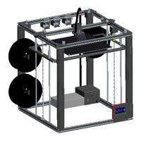
Filament loading requirements for mixing color printers.
Lists major part categories like brackets, screws, belts, sensors, and tools.
Includes SD card with user guide and provided tools.
Mount the hotend module to the bracket and install the X endstop.
Attach the proximity sensor to the hotend assembly.
Connect the hot bed using specified screws and nuts.
Attach the metal bracket to the X-axis motor.
Secure the timing pulley to the motor shaft using a jbckscrew.
Attach the metal bracket to the Y-axis motor.
Secure the timing pulley to the motor shaft using a jbckscrew.
Connect the left Z slider-rod bracket to the frame with slider rods.
Attach the Z-axis left slider component.
Connect the right Z slider-rod bracket to the frame.
Attach the Z-axis right slider component.
Insert T8 lead screws into the Z-axis drive mechanisms.
Place the closed timing belt onto the Z-axis pulleys.
Secure the lead screws by tightening the jbckscrews on the timing pulleys.
Move timing pulleys to the bottom and lock them with jbckscrews.
Labels indicating different aluminum profile types (Z9-A, Z9-B, etc.) on the printer frame.
Detailed dimensions and quantities for various aluminum profiles (Z9-Z, Z9-A, Z9-AP, etc.).
Diagram showing placement of top aluminum profiles and hole orientation.
Diagram showing placement of bottom aluminum profiles and hole orientation for the control box.
Join Z9-B and Z9-A profiles using HM5x20 screws to form the top frame.
Attach the left Y carrier to the top aluminum profile frame.
Attach the right Y carrier to the top aluminum profile frame, ensuring Y ENDSTOP alignment.
Assemble the top frame by connecting Z9-B profiles with HM5x20 screws.
Attach the X bearing bracket to the frame using HM5x20 screws.
Attach the Y bearing brackets to the frame using HM5x20 screws.
Install the X-axis drive component onto the frame.
Install the Y-axis drive component onto the frame, connecting to Y ENDSTOPS.
Attach the hotend assembly to the X-axis mechanism using screws and shims.
Join Z9-AP, Z9-BP, Z9-B, Z9-A profiles to form the bottom frame using HM5x20 screws.
Secure rubber pads to the bottom of the frame using M5x10 screws, shims, and nuts.
Attach vertical Z9-Z profiles to the bottom frame, ensuring big holes face downwards.
Install the left Z-axis drive mechanism onto the frame with the motor facing up.
Install the right Z-axis drive mechanism onto the frame.
Secure the top frame to the Z-axis profiles using HM5x30 screws.
Complete the top frame connection to the Z-axis profiles using HM5x20 screws.
Details on the Z9's CoreXY structure and motor correspondence for movement.
Explains clockwise and anticlockwise rotation of X and Y motors for movement.
Illustrates the routing of X (blue) and Y (red) motor belts on the bottom and top layers.
Steps for fixing and tightening X and Y belts to ensure perpendicularity.
Attach the hotbed bracket to the frame using PM3x6 screws.
Place the hot bed onto the bracket and secure with springs and hand nuts.
Attach the LCD screen to the right-bottom corner of the front frame.
Secure the filament roll bracket to the back Z-axis profiles.
Install the extrusion feeder onto the frame and connect the PTFE tube.
Explains using a synchronization belt to ensure left and right Z-axis alignment.
Instructions on tightening the Z-axis timing belt by rotating the idler after installation.
Loosen set screws on Z-axis timing pulleys to allow movement.
Manually rotate lead screws to lower the hotbed until copper nuts touch timing pulleys.
Retighten set screws to lock timing pulleys to the lead screws.
Adjust four hand nuts under the hot bed for even spacing.
Rotate coupling to raise hot bed until nozzle is near hot bed.
Adjust Z offset screw until Z ENDSTOP is triggered, then lock it.
Insert and hide wires in profile grooves, using plastic covers.
Install hotend wire clip to hold corrugated pipe.
Install a bellow seal joint to the control box.
Open the control box, wire hotend connections, and set voltage if needed.
Secure the control box to the bottom/back/right corner of the frame.
Details on routing Y, Z motor, and ENDSTOP wires along profile grooves.
Details on routing extrusion feeder and X motor wires along profile grooves.
Emphasizes caution with electrical connections and correct wiring to prevent damage.
Covers high current parts, wire management, and motor noise precautions.
Detailed pin assignments for motors, sensors, fans, and power on the ZRIBV6 board.
Pin assignments for EXP1, EXP2, and other expansion ports on the ZRIBV6 board.
Illustrates connections for motors, hotend, hotbed, fans, limit switches, and power supply.
Shows connections for USB, SD card, LCD, PC host, and optional components.
Warning about correct motor driver module orientation to prevent control board damage.
Guidance on adjusting drive current via potentiometer for stepper motors like X, Y, Z, and extruder.
Describes knob operations for navigating menus and adjusting values.
Explains displayed parameters like temperatures, feedrate, axis positions, and status messages.
Ensure the nozzle is clean before starting the leveling process.
Move the hotend to its origin position using the "Auto Home" function.
Adjust hotbed leveling nuts to achieve proper nozzle-to-bed distance.
Heat the nozzle to the required temperature before loading filament.
Feed filament into the extruder engine and hotend, ensuring smooth insertion.
Insert the SD card into the control box socket.
Choose a test file from the SD card and start the printing process.
Fine-tune Z offset during printing to ensure filament adhesion to the hotbed.
Convert 3D models into G-code files using slicing software.
Lists recommended slicing and host software like Repetier-Host, Cura, etc.
Provides links to cloud storage for slicing software guides and printer control instructions.
Extrude filament from both extruders simultaneously for mixed colors.
Adjust extruder mix rate during printing from SD card for color mixing.
Convert monochrome prints to multi-color prints automatically during the printing process.
Sensor to detect filament depletion; connectable to the Z5 control box.
Option to install a laser engine on the print head for laser engraving.
ZONESTAR's background as a high-tech manufacturer specializing in 3D printers since 2013.
ZONESTAR's commitment to Innovation, Quality, and Service.
| Build Volume | 300 x 300 x 400 mm |
|---|---|
| Filament Diameter | 1.75mm |
| Connectivity | USB, SD Card |
| Printing Technology | FDM (Fused Deposition Modeling) |
| Heated Bed | Yes |
| Bed Temperature | Up to 100°C |
| Nozzle Temperature | Up to 260°C |
| Nozzle Diameter | 0.4 mm |
| Supported Materials | PLA, ABS, TPU, Wood |
| Display | LCD |
| Display Type | LCD |
| Power Supply | 24V |
| Frame Material | Aluminum Extrusion |