16/ 63
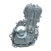
Cylinder head cover installation
1. As shown in the figure, after removing the plane sealant, oil stains and dust on the joint surface of the cylinder head
and the cylinder head cover, apply an appropriate amount of plane sealant on the position shown in the figure. Check
the cylinder head cover sealing ring and wire harness bracket on the cylinder head cover. After confirming that the
installation is in place, install the cylinder head cover assembly to the corresponding position of the cylinder head. Use
M6×30 bolts to pre-tighten the cylinder head cover and tighten it with a fixed torque, 1 2 ± 1.5N •m . And check the
installation of the high-pressure oil pipe support, pre-tighten the support with M6×10 bolts and tighten it with a fixed
torque, 1 0 ± 1 N•m .
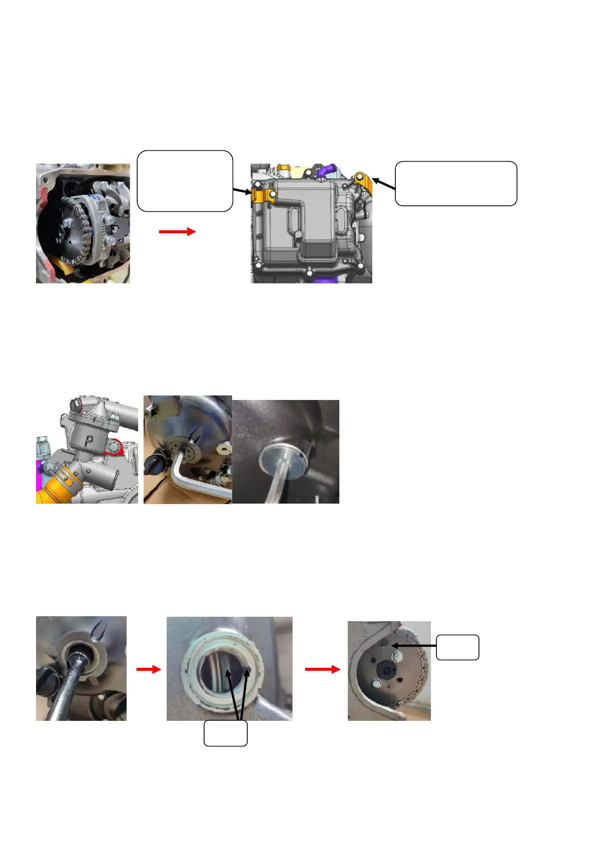
6. Cylinder head
Cylinder head removal
1. Use a T-shaped sleeve -8# to remove the thermostat bolt and take off the thermostat, and use the 5# and 10# inner
hexagonal wrench to remove the M14×1.5 screw plug and M30×1.5 screw plug on the right crankcase cover respectively.
Aluminum plug, and remove the O-ring.
2. Insert a 14#-T-type socket wrench from the M30×1.5 aluminum screw plug hole and set it on the magneto rotor locking
bolt, then turn the crankshaft clockwise to align the T point mark on the flywheel with the M14×1.5 screw. The plug hole
marks the gap. At the same time, the top dead center marking line on the timing driven sprocket should also be aligned
with the raised marking line on the cylinder head.
Note: Once the marking line at point T turns over the marking line when turning the flywheel, it cannot be turned
back to the point in the opposite direction. It is necessary to turn the crankshaft clockwise two times again to
re-align the point! ! !
Align
Short wheelbase
bracket
Long wheelbase only
with this bracket
 Loading...