Do you have a question about the Zte ZXMW NR8120A and is the answer not in the manual?
Procedure to check board status for fault detection and resolution.
Procedure to check board status for fault detection and resolution.
How to check current 24-hour performance data, using Ethernet as an example.
Procedure to check radio link performance data over the past 10 days.
How to check alarms for fault detection and timely resolution.
Procedure to check device events for fault detection and resolution.
Analyzing indicator status to locate faults on boards.
Ensures equipment operates properly by checking power supply.
Ensures equipment operates properly by checking power supply.
Describes how to clean equipment to reduce BER and failure rates.
Maintaining environmental conditions like temperature, humidity, and dust.
How to check receive level and handle out-of-range issues.
How to check receive level and handle out-of-range issues.
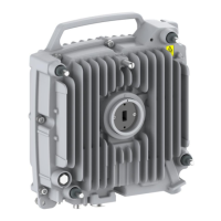
Verifies correct installation of the Outdoor Unit (ODU).
Ensures the combiner operates properly and cooperates with other devices.
Verifies the antenna installation for proper operation.
Ensures the IF cable is properly connected and installed.
Troubleshooting steps for a PC that cannot ping equipment via LMT.
Troubleshooting steps for a PC that cannot ping equipment via LMT.
Troubleshooting steps for a PC that cannot ping equipment via NMS.
Steps to address receive levels below the expected value.
Steps to address receive levels below the expected value.
Troubleshooting steps for radio link error codes.
Steps to troubleshoot a disconnected radio link.
Troubleshooting procedure for sudden link interruptions.
Procedure to troubleshoot when the MU loses its lock.
Steps to troubleshoot when air interface performance is zero.
Troubleshooting steps for TDM service faults.
Troubleshooting steps for Ethernet service faults.
Troubleshooting steps when network management services are disconnected.
Troubleshooting steps when network management services are disconnected.
Steps to troubleshoot when Network Elements (NEs) are out of control.
Procedure to perform the loopback test for transmission link problems.
How to check the Ethernet OAM function, using link connectivity as example.
How to check the Connectivity Fault Management (CFM) function.
How to check the Ethernet in the First Mile (EFM) function.
Forcedly migrate a port to MSTP or RSTP mode using M_Check operation.
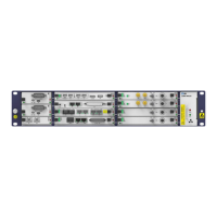
Description and status of indicators on the RCMUC board.
Description and status of indicators on the RCMUD board.
Description and status of indicators on the RTEA board.
Description and status of indicators on the RTEB board.
Description and status of indicators on the RFAD board.
| Brand | Zte |
|---|---|
| Model | ZXMW NR8120A |
| Category | Microphone system |
| Language | English |