Predator Installation Manual Ver 2.9 Page 14
© 360 Vision Technology Ltd.
1 2 3 4 5 6 7 8
CON4
Protocol Settings 3 4 5 6
360 Vision O O O O
Pelco D 9600 baud On O O O
Pelco D 4800 baud O On O O
Pelco D 2400 baud On On O O
Pelco P 9600 baud O O On O
Pelco P 4800 baud On O On O
Pelco P 2400 baud O On On O
Alarm Settings 7 8
Normal Operation O O
No Pre-alarm, No White Light On O
Forced White Light O On
No Pre-alarm, White Light Timer On On
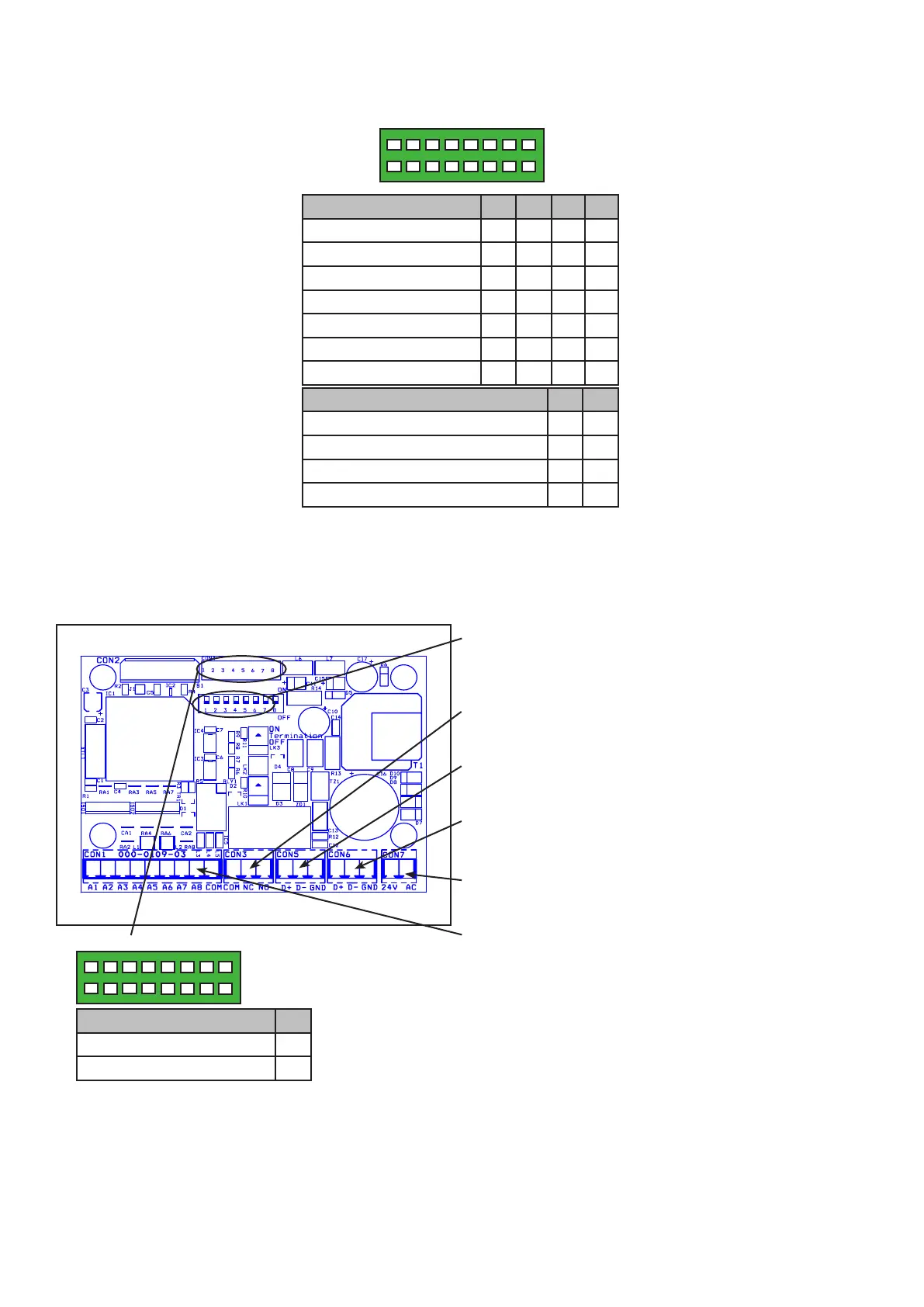
CON4 Settings
4.2 Washer Control PCB Setup
Power supplies ordered with a Washer function are shipped pre-built into the PSU weather proof box. The
washer control unit is programmed at manufacture to suit the protocol required and cannot be changed. No
further connections are required to this PCB during installation, but address must be set to suit.
Aux Settings 1
Aux 2 (Pelco default) O
Aux 3 (Pelco D 2400 only) On
1 2 3 4 5 6 7 8
CON4
Address (1-7) (Range 1 to 128)
Use Dilswitch to set address same as camera.
(see page 13)
Relay Output
Pre-wired CON3 for relay output to washer power PCB.
RS485 In Connections/LK3 termination
Connect RS485 from controller to CON5.
RS485 Out Connections
Pre-wired RS485 to camera from CON6.
Power Connections
Pre-wired 24Vac to CON7.
Inputs
CON1 not used.