Predator Installation Manual Ver 2.9 Page 18
© 360 Vision Technology Ltd.
6 Connections to Predators with HMA
When the HMA (Hinged Mount Adaptor) is tted to the Predator, the ‘Predator Composite Cable’ is not used.
Connections between the power supply and Predator use conventional cables as detailed below.
24Vac Power connections between Predator PSU and Predator that is tted with HMA
Cable Size No IR IR80 IR110WL IR130 IR175SW IR200
0.75mm² 20m 10m 7.5m 7.5m 6m N/A
1.00mm² 25m 12.5m 10m 10m 8m N/A
1.25mm² 30m 15m 12.5m 12.5m 10m N/A
1.50mm² 40m 20m 15m 15m 12m 4m
2.50mm² 65m 30m 25m 25m 20m 6.5m
3.00mm² 80m 40m 30m 30m 24m 8m
4.00mm² 100m 50m 40m 40m 32m 10.5m
If a thermal camera is tted in the Predator use a coax to connect the video signal BNC from Predator that is
tted with HMA and Predator PSU (PCB-000-0157-xx) CON6. This is used for the thermal camera video.
Gain access to connectors in the HMA
• Ensure that the xed part of the HMA is securely bolted to the top of the pole.
• The hinged part of the HMA (Hinged Mount Adapter) is fastened to the xed part using three M8x25
long hex head bolts. Use a spanner (13mm) to remove the three bolts. Each bolt is tted with a
split spring lock washer, a plain metal washer (which prevents the split washer from damaging the
bre washer) and a bre washer (which prevents the paint on the hinged part from being damaged
unnecessarily.
• Open the hinge taking care that the gasket is not damaged and support the weight of the Predator.
Gently open the HMA until the lanyard is able to take the weight. If the lanyard appears to support the
weight of the Predator, there is no need to continue to support the Predator. The connection circuit
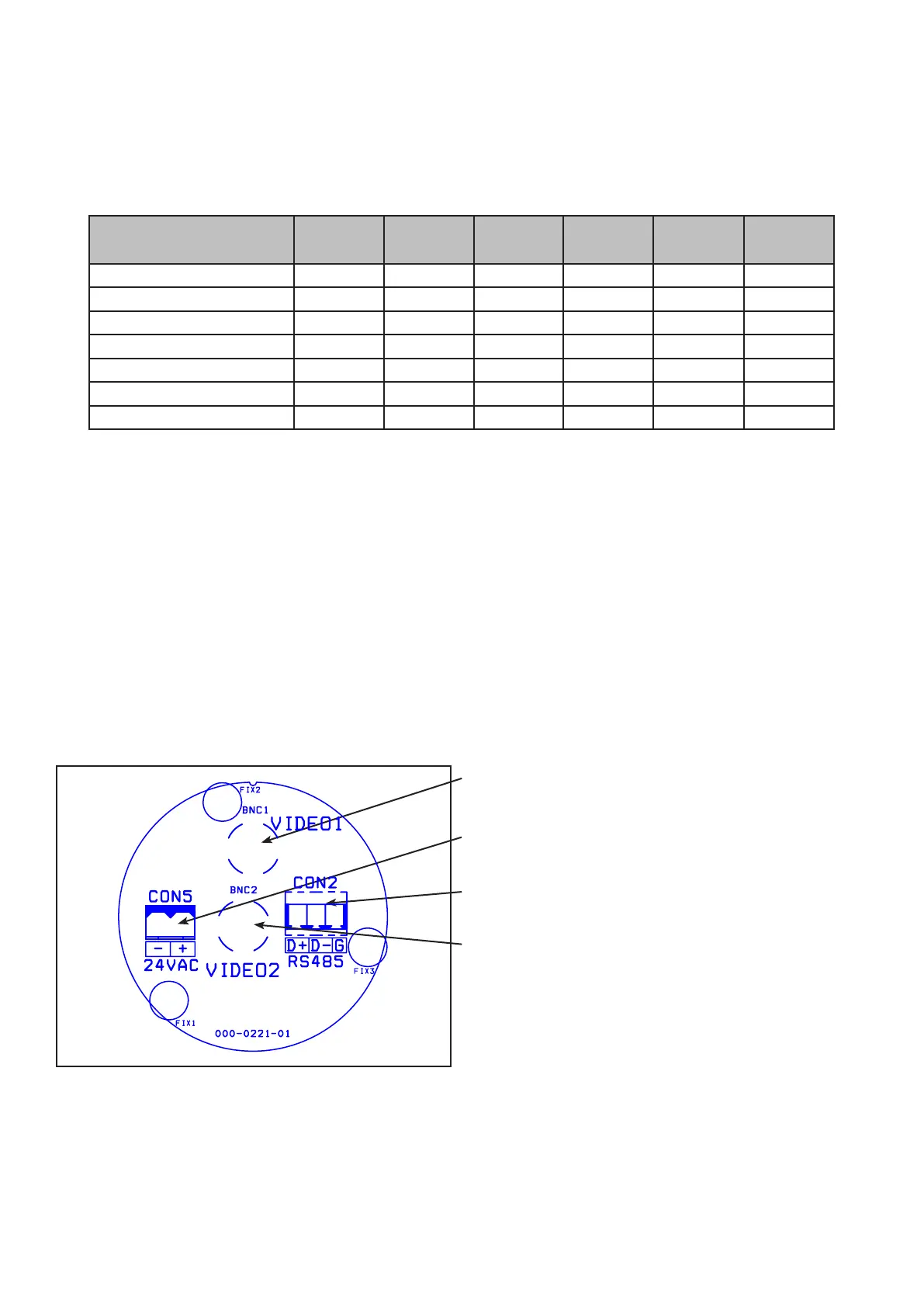
board (PCB-000-0221-01) can now be seen.
Please make sure there is adequate spare cable (20cm) for when the camera is resting on the lanyard, failure
to do this could damage the connector circuit board.
Camera
Use BNC Video 1 for video connection from Predator.
Power Connections
Connect 24Vac to CON5.
RS485 Connections
Connect RS485/Twisted Pair data cable to CON2.
Thermal Camera (If present)
Use BNC Video 2 for thermal video connection from
Predator.