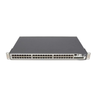
38 CHAPTER 2: INSTALLING THE SWITCH
Specifying the
Redundant Power
System
3Com’s redundant power solution allows you to use any off-the-shelf
-48V DC RPS that meets the requirements defined in
Appendix C on
page 127.
For an approved vendor list, more details about purchasing the 3Com
recommended RPS, and a full set of requirements go to:
http://www.3Com.com/RPS
The 3Com recommended RPS generates -48V DC power using power
supply units (or rectifiers). The outputs of the rectifier(s) are connected
together so that you can increase the total -48V power available by
adding rectifiers. For example, three 1500W rectifiers can provide up to
4500W. Hot removal or insertion of a rectifier does not affect the -48V
DC output voltage.
Tabl e 14 shows an example of the total power available from several
1500W rectifiers.
A minimum of two rectifiers are required for each shelf to provide N+1
rectifier redundancy.
Table 14 Power Availability
The unearthed -48V DC power distribution provides the mechanism to
connect to the Switch 5500. The distribution consists of several circuit
breakers and connection terminals for the positive (common) and
negative -48V outputs. Individually connect each Switch 5500 to a circuit
breaker terminal.
You can also connect a battery to battery terminals prior to the DC power
distribution to provide uninterrupted power and to be protected against
the loss of AC mains power.
Rectifiers
1 2 3 4 5 6
No Rectifier
Redundancy
1500W 3000W 4500W 6000W 7500W 9000W
N+1 Rectifier
Redundancy
- 1500W 3000W 4500W 6000W 7500W