Tabl e 13 lists the V.25 DCE cable pinouts.
V.35 DTE Cable
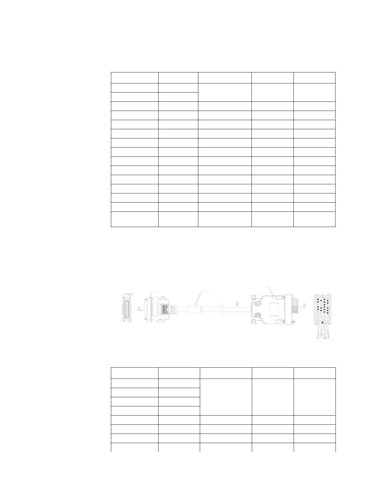
The V.35 DTE cable has a 34PIN (male) connector at the network end. Figure 9
illustrates the V.35 DTE cable.
Figure 9 V.35 DTE Cable
Tabl e 14 lists the V.35 DTE cable pinouts.
Tabl e 13 V.25 DCE Cable Pinouts
DB28 Signal Signal direction DB25 (female) Signal
6 GND <--> 7 Circuit GND
7 MODE0
21 GND <--> 1 Shield GND
19 RXD+ <- 2 TXD
1 TXD+ -> 3 RXD
23 CTS+ <- 4 RTS
13 RTS+ -> 5 CTS
25 DSR+ <- 20 DTR
27 DTR+ -> 6 DSR
15 TXCE+ -> 17 RXC
3 TXC+ -> 15 TXC
17 RXC+ <- 24 ETC
11 DCD+ -> 8 DCD
22 LL <- 18 LTST
Shielding shell Core-shielding
layer
<--> Shielding shell Core-shielding
layer
Tabl e 14 V.35 DTE Cable Pinouts
DB28 Signal Signal direction 34PIN (male) Signal
6 GND <--> A Circuit GND
10 MODE_DCE
7 MODE0
8 MODE1
21 GND <--> B Shield GND
1 TXD+ -> P SD+
2 TXD- -> S SD-
19 RXD+ <- R RD+
Enlarged A side Enlarged B side
DB28 Male
V.35 Male
Label
3Com Router Release Notes for V1.20
 Loading...