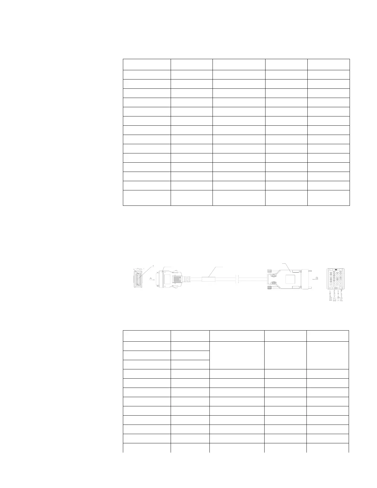
V. 3 5 D C E C a b l e
The V.35 DCE cable has a 34PIN (female) connector at the network end. Figure 10
illustrates the V.35 DCE cable.
Figure 10 V.35 DCE Cable
Tab le 15 lists V.35 DCE cable pinouts.
20 RXD- <- T RD-
13 RTS+ -> C RTS
23 CTS+ <- D CTS
27 DTR+ -> H DTR
25 DSR+ <- E DSR
17 RXC+ <- V SCR+
18 RXC- <- X SCR-
3 TXC+ ? Y SCT+
4 TXC- ? AA SCT-
15 TXCE+ -> U SCTE+
16 TXCE- -> W SCTE-
11 DCD+ <- F RLSD
22 LL -> J LL
Shielding shell Core-shielding
layer
<--> Core-shielding
layer
Shielding shell
Table 15 V.35 DCE Cable Pinouts
DB28 Signal Signal direction 34PIN (female) Signal
6 GND <--> A Circuit GND
7 MODE0
8 MODE1
21 GND <--> B Shield GND
19 RXD+ <- P TXD+
20 RXD- <- S TXD-
1 TXD+ -> R RXD+
2 TXD- -> T RXD-
23 CTS+ <- C RTS
13 RTS+ -> D CTS
25 DSR+ <- H DTR
27 DTR+ -> E DSR
Table 14 V.35 DTE Cable Pinouts (continued)
DB28 Signal Signal direction 34PIN (male) Signal
Enlarged A side
DB28 Male
V.35 Female
Label
Enlarged B side
3Com Router Release Notes for V1.20
 Loading...