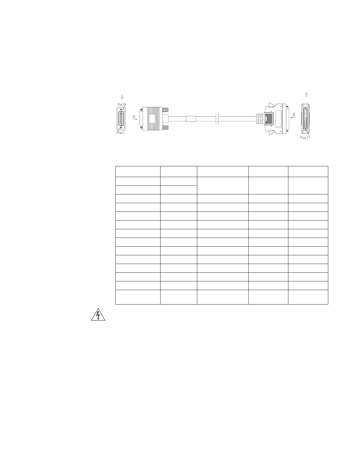
X.21 DCE Cable
The X.21 DCE cable has a DB15 (female) connector at the network end. Figure 12
illustrates the X.21 DCE cable.
Figure 12 X.21 DCE Cable
Tab le 17 lists the X.21 DCE cable pinouts.
Warning: To prevent damage to the router and ports, do not connect or
disconnect the interface cable to the 4-port synchronous/asynchronous serial
module with X.21 while the router is powered on.
Before connecting the 4-port synchronous/asynchronous serial module with X.21,
confirm the mode of the equipment that is connected to it (the synchronous/
asynchronous mode, DTE/DCE mode of the peer, and so on), the signaling
criterion required by the access equipment, baud rate, and synchronous clock.
To connect cables to the 4-port synchronous/asynchronous serial module with
X21:
1 Power off the router.
2 Verify the interface type of the peer device and choose the synchronous/
asynchronous serial interface cable of correct type.
Table 17 X.21 DCE Cable Pinouts
DB28 Signal Signal direction DB15 (female) Signal
6 GND <--> 8 Circuit GND
9 MODE2
21 GND <--> 1 Shield GND
13 RTS+ -> 5 Indication+
14 RTS- -> 12 Indication -
23 CTS+ <- 3 Control+
24 CTS - <- 10 Control -
19 RXD+ <- 2 Transmit+
20 RXD- <- 9 Transmit +
1 TXD+ -> 4 Receiver+
2 TXD - -> 11 Receiver -
15 TXCE+ -> 6 Timing+
16 TXCE - -> 13 Timing -
Shielding shell Core-shielding
layer
<--> Core-shielding
layer
Shielding shell
3Com Router Release Notes for V1.20
 Loading...