3 Plug the DB-28 end of the connection cable to the corresponding DB-28 interface
in the 4-port synchronous/asynchronous serial module with X.21.
4 Connect the other end of the cable as appropriate:
■ If the WAN is a leased line, connect the cable to the interface of the CSU/DSU.
■ If the WAN is a dialup line, connect the cable to the serial interface of the
analog modem.
5 Power on the router, and check the status of the LINK LED on the faceplate of the
router. It flashes green when the module has completed the self-check and works
normally. The LINK LED is off if the module fails to pass the self-check or if the line
is faulty and the signal is out of step, as described in
Tab le 11. If the LINK LED is
off, contact your Service representative.
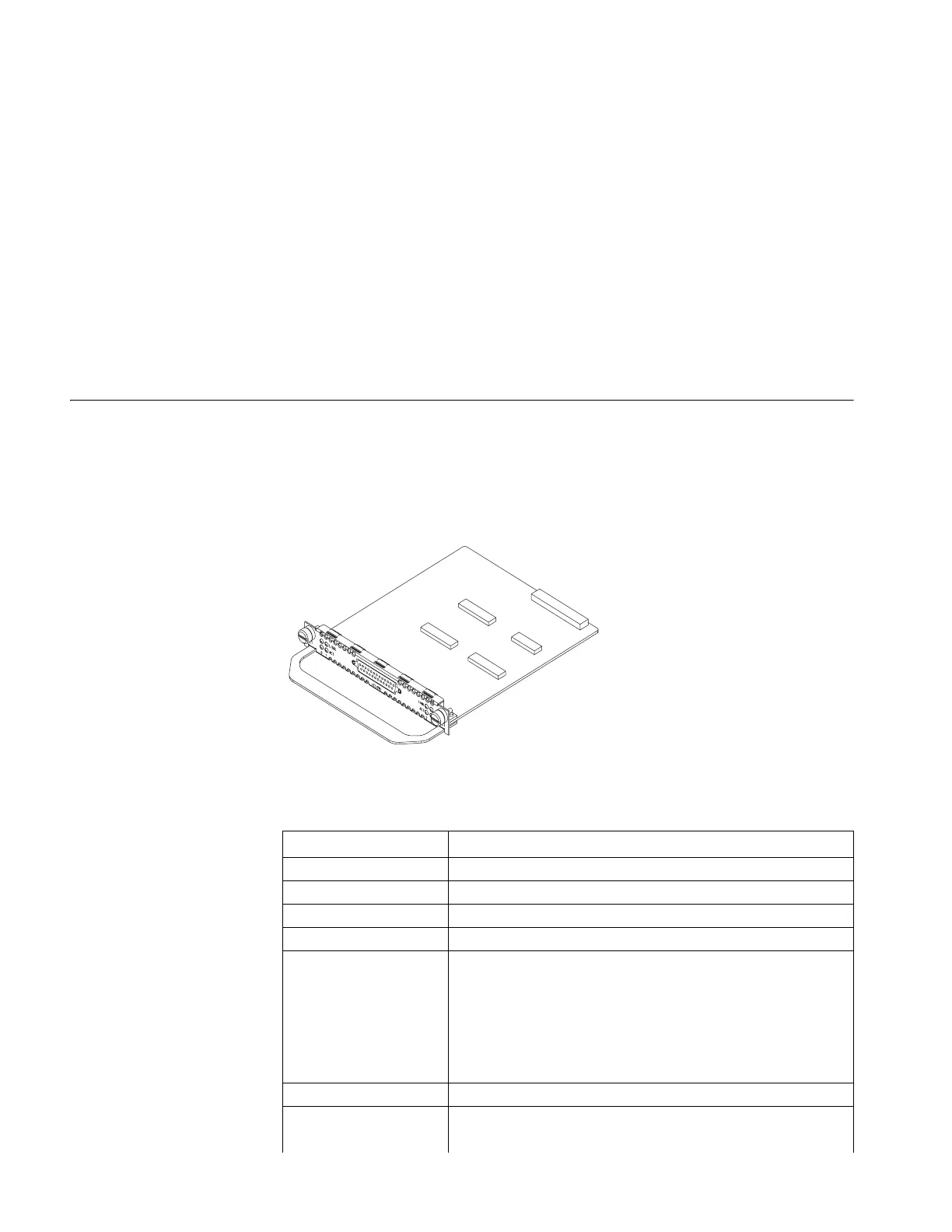
4-Port E1/CE1/PRI MIM The main function of the 4-port E1/CE1/PRI module is to implement the
transceiving and processing of E1 data streams. In addition, it provides access to
CE1, and implements the ISDN PRI function so that one board can serve multiple
purposes.
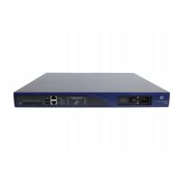
Figure 13 illustrates a 4-port E1/CE1/PRI module.
Figure 13 The 4-Port E1/CE1/PRI Module
Features Tabl e 18 lists features of the 4-port E1/CE1/PRI module.
Tabl e 18 Features of the 4-Port E1/CE1/PRI Module
Attribute Description
Connector DB-25
Number of connectors 1
Interface standard G.703, G.704
Interface speed 2.048Mbps
Cables E1 75-ohm non-balanced coaxial cable
E1 120-ohm balanced twisted pair cable
120-ohm 4E1 conversion cable
75-ohm 4E1 conversion cable
Coaxial connector, network interface connector and 75-ohm to
120-ohm adapter (with BNC connector)
Operating mode E1, CE1, ISDN PRI
Network protocols
supported
1) IP
2) Novell IPX
3Com Router Release Notes for V1.20
 Loading...