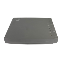
Faceplate and LEDs Figure 6 illustrates the faceplate of the 4-port synchronous/asynchronous serial
module with X.21.
Figure 6 Faceplate of the 4-Port Synchronous/Asynchronous Serial Module with X.21
Tabl e 11 lists the status descriptions of the 4-port synchronous/asynchronous serial
module with X.21 LEDs.
Cable The 4-port synchronous/asynchronous serial module with X.21 uses a
synchronous/asynchronous serial interface cable with a DB28 connector.
Before connecting to the 4-port synchronous/asynchronous serial module with
X.21, confirm the line properties. There are six optional cables depending on
different line properties. These six cables are optional and are not automatically
provided so you must order one with your 4-port synchronous/asynchronous serial
module with X.21 support.
■ V.24 (RS232) DTE Cable
■ V.24 (RS232) DCE Cable
■ V.35 DTE Cable
■ V.35 DCE Cable
■ X.21 DTE Cable
■ X.21 DCE Cable
One end of the cables is connected to the router side by a DB-28 connector. The
connector at the other end of the cable varies with the requirements of the
network side to which it is connected.
Protocols
supported
1) PPP
2) MP
3) LAPB
4) X.25
5) HDLC
6) SDLC
7) Frame Relay
1) PPP
2) SLIP
3) MP
Table 10 Features of the 4-Port Synchronous/Asynchronous Serial Module with X.21
Attribute Description
Tabl e 11 4-Port Synchronous/Asynchronous Serial Module with X.21 LEDs
LINK Off: The link is not connected.
Green: The link is connected.
ACT Off: No data is being transceived.
Flashing green: Data is being transceived.
3Com Router Release Notes for V1.20
 Loading...