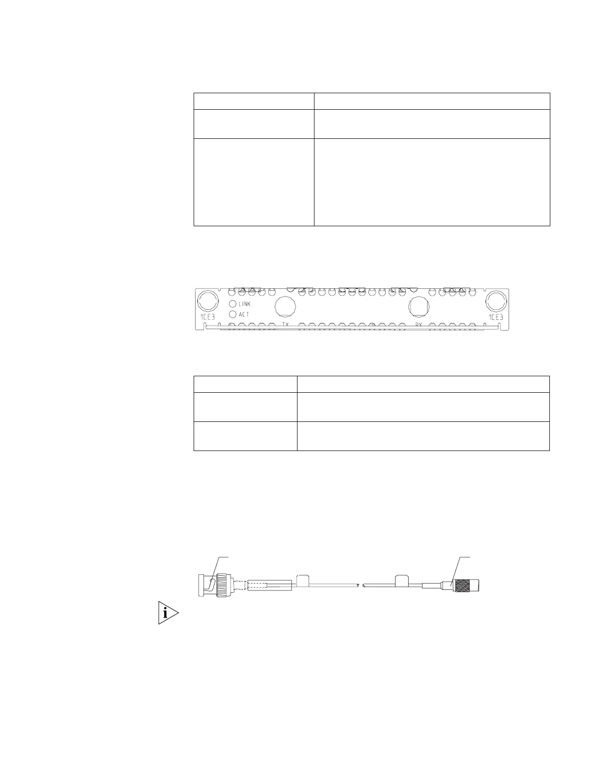
Faceplate and LEDs Figure 20 illustrates the faceplate of the 1-port channelized E3 module.
Figure 20 Faceplate of the 1-Port Channelized E3 Module
The following table lists the meanings of the LEDs on the faceplate.
Cables The external interface provided by a 1-port channelized E3 module is two SMB
sockets respectively for Tx (Transmitter end) and Rx (Receiver end). The interface
uses the 75ohm unbalanced transmission mode and uses a pair of 75ohm
unbalanced coaxial cables to connect the peer device.
Figure 21 E3/T3 cable
Note:
1) The 1-port channelized E3 and 1-port channelized T3 modules use the same E3/
T3 cable.
Supported network protocol IP
IPX
Protocols supported X.25
Frame Relay
PPP
MP
HDLC
LAPB
Table 23 Features of the 1-Port Channelized E3 Module (continued)
Attribute Description
Table 24 1-Port Channelized E3 Module LEDs
LED Meaning
LINK OFF: The link is not set up.
ON: The link has been set up.
ACT OFF: No data is being transmitted or received.
Flashing green: Data is being transmitted and received.
BNC connector
SMB connector
3Com Router Release Notes for V1.20
 Loading...