Weighting Characteristics ................................................................................................. 14
Internal Electrical Noise .................................................................................................... 14
Tone Burst Response ....................................................................................................... 15
Specifications ................................................................................................................. 16
Accessories .................................................................................................................... 18
Quest Service ................................................................................................................. 19
Contacting Quest Technologies ........................................................................................ 19
International customers .................................................................................................... 19
Figures
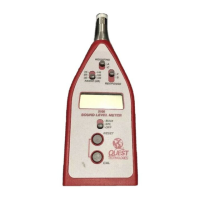
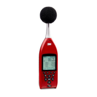
Figure 1-1: Sound Level Meter 2100 model ....................................................................1
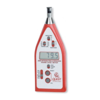
Figure 1-2: Model 1100R/2100R ....................................................................................2
Figure 2: Keypad/Control switches identified ...............................................................4
Figure 3: Output jack connections ...............................................................................5
Figure 4: Effects of background noise ...........................................................................9
Figure 5: Effects of WS-7 ...........................................................................................9
Figure 6: Block diagram of the model 1100/2100’s circuit board .................................. 11
Figure 7: Typical microphone response Type 1 ......................................................... 12
Figure 8: Typical microphone response Type 2 ......................................................... 12
Figure 9: Frequency/Amplitude limitations with extension cables ................................ 13
Figure 10: Input buffer circuitry ................................................................................... 13
Figure 11: A & C Weighting ........................................................................................ 14
Figure 12: Fast response ........................................................................................... 15
Figure 13: Slow response .......................................................................................... 15
 Loading...