6009S Mercury Vapor/Sulfur Dioxide/
Chlorine Gas
Mercury vapor, sulfur dioxide or chlorine gas
60921 Organic Vapor/P100 Certain organic vapors and particulates
60921i Organic Vapor with Service Life
Indicator/P100
Certain organic vapors and particulates
60922 Acid Gas/P100 Chlorine, hydrogen chloride, and sulfur dioxide
or chlorine dioxide or hydrogen sul de and
particulates
60923 Organic Vapor/Acid Gas/P100 Certain organic vapors, chlorine, hydrogen chloride,
and sulfur dioxide or hydrogen sul de or hydrogen
uoride and particulates
60924 Ammonia/Methylamine/P100 Ammonia and methylamine and particulates
60925 Formaldehyde/Organic Vapor/
P100
F
1
ormaldehyde and certain organic vapors and
particulates
60926 Multi-Gas/Vapor/P100 Certain organic vapors, chlorine, hydrogen chloride,
chlorine dioxide, sulfur dioxide, hydrogen sul de,
ammonia/methylamine,
1
formaldehyde or hydrogen
uoride and particulates
60928 Organic Vapor/Acid Gas/P100 Certain organic vapors, chlorine, hydrogen chloride,
and sulfur dioxide or hydrogen sul de or hydrogen
uoride and particulates
2
60929S Mercury Vapor/Sulfur Dioxide/
Chlorine Gas/P100
Mercury vapor, sulfur dioxide or chlorine gas and
particulates
**** AAD part numbers are catalog numbers only. NIOSH approved as PSD part numbers
1
OSHA regulations require gas proof goggles be worn with half facepiece respirators when used against
formaldehyde.
2
3M recommended for use against methylbromide or radioiodine up to 5 ppm with daily cartridge replacement.
NOTE: Not NIOSH approved for use against methylbromide or radioiodine.
Service Life of Chemical Cartridges and Particulate Filters
3M™ Cartridges 6000 Series should be used before the expiration date on cartridge packaging. The useful
service life of these cartridges will depend upon the activity of the wearer (breathing rate), speci c type, volatility
and concentration of contaminants and environmental conditions such as humidity, pressure, and temperature.
Cartridges must be replaced in accordance with an end of service life indicator (ESLI), established change schedule,
regulations, or earlier if smell, taste or irritation from the contaminant is detected.
Particulate lters must be replaced if they become damaged, soiled or if increased breathing resistance occurs.
N-series should not be used in environments containing oils. R-series lters may be limited to 8 hours of continuous
or intermittent use if oil aerosols are present. In environments containing only oil aerosols, P-series lters should be
replaced after 40 hours of use or 30 days, whichever is rst.
3M™ Filters/Adapters/Retainers
NOTE: Only 3M™ Filters approved under NIOSH 42 CFR 84 are to be used with the 3M™ Half Facepiece 7500 Series.
Number ****AAD
501 07054
502
603
2071
2076HF
Description
Filter Retainer for Filters 5N11 and 5P71
Filter Adapter for Filters 2000 Series and 7093/7093C
Filter Adapter for Filters 5N11, 5P71 with Filter Retainer 501
Particulate Filter, P95
Particulate Filter, P95, hydrogen uoride, with nuisance level acid
gas relief
1
2078 Particulate Filter, P95, 3M recommended ozone protection
2
, with
nuisance level organic vapor/acid gas relief
1
2091 07000
2291
2096
Particulate Filter, P100
Advanced Particulate Filter, P100
Particulate Filter, P100, with nuisance level acid gas relief
1
2296 Advanced Particulate Filter, P100, with nuisance level acid gas relief
1
2097 07184 Particulate Filter, P100, 3M recommended for ozone protection
2
,
nuisance level organic vapor relief
1
2297
5N11
Advanced Particulate Filter, P100, 3M recommended for ozone
protection
2
, nuisance level organic vapor relief
1
Particulate Filter, N95
5P71 07194 Particulate Filter, P95
7093 Particulate Filter, P100
7093C 37173 Particulate Filter, P100, hydrogen uoride with nuisance level organic
vapor/acid gas relief
1
**** AAD part numbers are catalog numbers only. NIOSH approved as PSD part numbers
1
3M recommended for relief against nuisance levels of acid gases or organic vapors. Nuisance level refers to
concentrations not exceeding OSHA PEL or applicable government occupational exposure limits, whichever is
lower. Do not use for respiratory protection against acid gases or organic vapors.
2
3M recommended for ozone protection up to 10 times the OSHA PEL or applicable government occupational
exposure limits, whichever is lower. NOTE: Not NIOSH approved for use against ozone.
3M™ Particulate Filters must be immediately changed when an increase in breathing resistance is noticed.
In Brazil, the 3M™ Filter 5935BR can be used with the Filter Adaptor 603 and the Filter Retainer 501 on the 3M™
Half Facepiece 7500 Series.
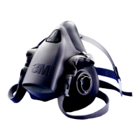
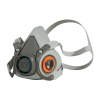
ASSEMBLY INSTRUCTIONS
3M™ Cartridge Assembly 6000 Series
Align cartridge notch with arrow on facepiece, as shown, and push together (Fig. 1). Turn cartridge clockwise to stop
(1/4 turn) (Fig. 2).
3M™ Filter Assembly 5N11 and 5P71
1. Place lter into 3M™ Retainer 501 *(07054) so printed side of lter faces the cartridge (Fig. 3).
2. Press cartridge into lter retainer. It should snap securely into lter retainer. When correctly installed, lter
should completely cover face of cartridge.
3. To replace lter, remove retainer by lifting on TAB.
3M™ Filters, 2000 Series and 7093/7093C Filter Assembly
Align opening of lter with lter attachment on facepiece. Turn lter clockwise until it is rmly seated and cannot be
further turned. Repeat for second lter.
3M™ Filter Adapter 502 Assembly and Filter Attachment
1. Align adapter over cartridge. Engage front snap by squeezing front of cartridge and adapter together, placing
thumbs of both hands over top of adapter and ngers along bottom sides of cartridge (Fig. 4).
2. Engage back snap by squeezing back side of cartridge and adapter together using the same hand positions
(Fig.5). An audible click should be heard as each snap is engaged.
3. Place lter onto the lter holder so that lter comes into even contact with gasket. Twist clockwise a quarter
turn until it is rmly seated and lter cannot be turned further. Repeat for second lter.
NOTE: The 3M™ Filter Adapter 502, once installed on a 3M™ Cartridge 6000 Series, is not to be removed or
reused. Removal or reuse may result in leakage, overexposure, sickness or death.
3M™ Filters, 2000 Series and 7093/7093C with 3M™ Filter Adapter 502
Place lter onto the lter holder so that lter comes into even contact with gasket. Twist clockwise one quarter, turn
until it is rmly seated and lter cannot be turned further. Repeat for second lter.
NOTE: The 3M™ Filter Adapter 502, once installed on a 3M™ Cartridge 6000 Series, is not to be removed or
reused. Removal or reuse may result in leakage, overexposure, sickness or death.
3M™ Filter Adapter 603 Assembly and 5N11 or 5P71 Filter Attachment
1. Align notch on edge of 603 adapter with facepiece mark as shown (Fig. 22).
2. Turn adapter 1/4 turn clockwise to stop. To remove adapter, turn 1/4 turn counterclockwise (Fig. 23).
3. Place lter into 501 retainer with lter printing facing towards the 603 adapter. Snap together and ensure the
lter seal is free from creases or gaps (Fig. 24).
In Brazil, the 5935BR Filter used with the 603 adaptor is assembled following the same procedures as the 5N11
and 5P71.
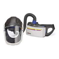
3M™ Supplied Air Systems
W WARNING
To meet the U.S. National Institute for Occupational Safety and Health (NIOSH) requirement for minimum
(4CFM/115 lpm) and maximum (15 CFM/424 lpm) air ow, the air control valves approved for use with the 3M™
Half Facepiece Respirators 7500 Series must be operated within the correct supply pressure ranges and hose
lengths. Failure to do so may result in sickness or death.
In Brazil, the Brazilian Association of Technical Standards (ABNT) NBR 14372 requires a minimum of 120 lpm and
maximum of 280 lpm air ow for breathing air for half and full facepiece respirators.
W WARNING
OSHA standard 29 CFR 1910.134 requires that employers provide breathing air which shall “meet at least the
requirements of the speci cation for Grade D breathing air as described in Compressed Gas Association Commodity
speci cation G-7.1-1997” in the United States. In Canada, breathing air systems must be supplied air which meets
at least the requirements of CSA Standard Z180.1. Failure to do so may result in sickness or death.
In Brazil breathing air systems must be supplied with air, which meets ANSI Z86.1-1989/CGA G-7.1, Grade D
breathing air.
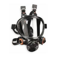
Assembly of 3M™ Dual Airline Breathing Tubes
1. Hold the facepiece in front of you so that the 3M logo is facing you. Align the two branches of the breathing tube
over the two bayonet mounts on facepiece. For the 3M™ Breathing Tubes SA-1500 or SA-1600, make sure
that 3M logo on breathing tube and on half facepiece are both facing towards you. For 3M™ Breathing Tubes
SA-2500 *(07148) or SA-2600 *(37001), make sure that the 3M logo on breathing tube is facing in opposite
direction to 3M logo on half facepieces (Fig. 6). SA-1500/SA-2500 shown.
2. Twist each branch of breathing tube clockwise a quarter turn until it is rmly seated in the bayonet and cannot
be turned further (Fig. 7 and 8). Do not forcibly overturn as the bayonet could be damaged. SA-1500/SA-2500
shown.
3. Attach airline to approved air regulators per pressure schedules in dual airline, supplied air respirators
User Instructions.
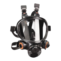
Assembly of 3M™ Combination Dual Airline Breathing Tubes with Cartridges
and/or Filters
The SA-1600 (front-mounted) and SA-2600 *(37001) (back-mounted) versions of the 3M™ Dual Airline Breathing
Tubes allow use of selected, NIOSH-approved 6000 series cartridges and 2000 Series lters. For listing of approved
cartridges and lters, reference NIOSH approval label included with 3M dual airline breathing tubes with cartridges
and/or lters.
1. Attach SA-1600 or SA-2600 breathing tubes to facepiece per the procedures outlined previously. The procedure
is identical to the SA-1500 and SA-2500 *(07148) models.
2. Make a selection of cartridges and/or lters that meets your respiratory protection requirements, and attach to
the outer bayonets of SA-1600 or SA-2600 breathing tubes (Fig. 9).
3. Don facepiece per procedures outlined in Donning Respirator instructions.
4. After being properly t tested, perform a positive and negative pressure user seal check each time the respirator
is donned per procedures outlined in User Seal Check instructions.
If you cannot achieve a proper t, DO NOT enter contaminated area. See your supervisor.
Using the 3M™ Combination Dual Airline Breathing Tubes without Cartridges
and/or Filters
To use the 3M™ Breathing Tubes SA-1600 or SA-2600 *(37001) without cartridges or lters, attach a 3M™
Bayonet Cap 6880 *(37002) to each outer bayonet mount on the breathing tube. When used as a straight, Type C,
continuous ow supplied air respirator, the Assigned Protection Factor is 50 times the PEL or TLV guidelines for half
facepiece respirators.
FITTING INSTRUCTIONS
Must be followed each time respirator is worn.
The 7500 series half facepiece suspension can be con gured as a standard xed suspension or a drop down
suspension for individuals using hard hats. Position straps beneath locking tabs for standard xed suspension
(Fig.10) or position straps over locking tabs for optional drop down suspension (Fig. 11).
NOTE: Do not use with beards or other facial hair or other conditions that prevent a good seal between the face and
the faceseal of the respirator. To help maintain a good seal between the face and the faceseal all hair, hoods, or other
equipment must be kept out of respirator faceseal area at all times.
Donning (Standard Suspension)
1. Adjust head cradle size as needed to t comfortably on head. Place the respirator over the mouth and nose,
then pull the head harness over the crown of the head. Grasp the bottom straps, place them at the back of the
neck and hook them together.
2. Pull the ends of the straps to adjust the tightness. Do not over-tighten (Fig. 13).
3. Perform a positive and/or negative pressure user seal check each time the respirator is donned.
If you cannot achieve a proper t, DO NOT enter contaminated area. See your supervisor.
Donning (Drop Down Suspension)
1. Adjust head cradle size as needed to t comfortably on head.
2. While holding head harness strap ends with one hand, slide the facepiece up onto your face (Fig. 12). Next
grasp strap ends with each hand and hook them together at back of neck.
3. Adjust strap tension by pulling strap ends until a secure t is obtained. Balance strap tension by adjusting at
top and bottom strap buckles. Do not over tighten. (Strap tension may be decreased by pushing out on back
side of buckles.)
4. Perform a positive and/or negative pressure user seal check each time the respirator is donned. If you cannot
achieve a proper seal, DO NOT enter contaminated area. See your supervisor.
User Seal Checks
Always check the seal of the respirator on your face before entering a contaminated area.
Positive Pressure User Seal Check
1. Cover the opening in exhalation valve cover with hand and exhale gently (Fig. 14). If facepiece bulges slightly
and no air leaks are detected between your face and facepiece, a proper seal has been obtained.
2. If faceseal air leakage is detected, reposition respirator on your face and/or readjust tension of the elastic straps
to eliminate leakage.
If you cannot achieve a proper seal, DO NOT enter contaminated area. See your supervisor.
Negative Pressure User Seal Check (with 6000 Series Cartridges)
NOTE: Use of 3M™ Filter Retainer 501 may aid respirator wearer in conducting a negative pressure user seal check.
1. Place palms of hands to cover face of cartridge or open area of 3M™ Filter Retainer 501 *(07054), when
retainer is attached to the cartridge, to restrict air ow (Fig. 15).
2. Inhale gently. If you feel facepiece collapse slightly and pull closer to your face with no leaks between the face
and facepiece, a proper seal has been obtained.
3. If faceseal air leakage is detected, reposition respirator on face and/or readjust tension of straps to eliminate
air leakage.
If you cannot achieve a proper seal, DO NOT enter contaminated area. See your supervisor.
Negative Pressure User Seal Check (with 2000 series lters)
1. Place your thumbs onto the center portion of the lters, restricting air ow into the breathing tube of lters, and
inhale gently. If you feel facepiece collapse slightly and pull closer to your face with no leaks between the face
and facepiece, a proper seal has been obtained (Fig. 16).
2. If faceseal air leakage is detected, reposition respirator on face and/or readjust tension of straps to eliminate
the leakage.
If you cannot achieve a proper seal, DO NOT enter contaminated area. See your supervisor.
Negative Pressure User Seal Check (with 7093/7093C lters)
1. Using hands press or squeeze lter covers toward facepiece and inhale gently. If you feel facepiece collapse
slightly and pull closer to your face with no leaks between the face and facepiece a proper seal has been
obtained. (Fig. 25).
2. If faceseal air leakage is detected, reposition respirator on face and/or readjust tension of straps to eliminate the
leakage.
If you cannot achieve a proper seal, DO NOT enter contaminated area. See your supervisor.
Negative Pressure User Seal Check with Dual Airline
1. Disconnect airline hose from air control valve.
2. With breathing tube still connected to the air control valve inhale gently. If you feel facepiece collapse slightly
and pull closer to your face with no leaks between the face and facepiece, a proper seal has been obtained.
3. For combination dual airline where cartridges or lters are attached perform user seal check as described
above under the appropriate cartridge or lter that is being used.
4. If faceseal air leakage is detected, reposition the respirator on your face and/or readjust the tension of the
straps to eliminate the leakage and recheck seal.
If you cannot achieve a proper seal, DO NOT enter contaminated area. See your supervisor.
NOTE: Before assigning any respirator to be worn in a contaminated area, a qualitative or quantitative t test
must be performed per OSHA Standard 1910.134 or CSA Standard Z94.4.
Fit Testing
The effectiveness of a respirator will be reduced if it is not tted properly. Therefore, either quantitative or qualitative
t testing must be conducted prior to the respirator being issued and used.
NOTE: Fit testing is a U.S. Occupational Safety and Health Administration (OSHA), a Canadian CSA and a Brazilian
BMOL requirement.
Quantitative Fit Testing
To conduct a quantitative t test (QNFT) with the 3M™ Half Respirator Facepiece, 7501 *(37081), 7502 *(37082),
7503 *(37083), place a 3M™ Fit Test Adapter 601 on either side of the half facepiece. Place a 3M™ Filter 2091 or
3M™ Filter P100 7093 on the 601 t test adapter and the other side of the half facepiece.
Qualitative Fit Testing
Qualitative Fit Testing (QLFT) can be conducted with any approved particulate lters. The FT-10 (sweet) or FT-30
(bitter) QLFT t test can be utilized to conduct the t testing.
Fit testing should be conducted using the heaviest cartridge, canister, lter or combination that each wearer will use
in their work environment. Respirators should also be t tested while wearing any personal protective equipment
(PPE) the wearer may use in their work environment that may affect the t of the respirator (e.g. hoods, hardhats,
safety glasses, hearing protections, etc.).
INSPECTIONS, CLEANING AND STORAGE
Inspection Procedure
This respirator must be inspected before each use to ensure it is in proper operating condition. Any damaged or
defective parts must be replaced before use. The following procedure is recommended:
1. Check the facepiece for cracks, tears and dirt. Examine the inhalation valves for signs of distortion, cracking or
tearing.
2. Check that the head straps are intact and have good elasticity.
3. Examine all plastic parts and gasket areas for signs of cracking or fatiguing and replace if necessary. Remove
the exhalation valve cover and examine the exhalation valve and seat for signs of dirt, distortion, cracking, or
tearing. Replace the valve if necessary. Secure the valve cover prior to use (Fig. 17).
Cleaning and Storage
Cleaning is recommended after each use
W WARNING
Do not clean with solvents. Cleaning with solvents may degrade some respirator components and reduce
respirator effectiveness. Inspect all respirator components before each use to ensure proper operating condition.
Failure to do so may result in sickness or death.
1. Remove cartridges and/or lters.
2. Clean facepiece (excluding lters and cartridges), with 3M™ Respirator Wipes 504 *(07065) (not to be used
as the only method of cleaning) or by immersing in warm cleaning solution, water temperature not to exceed
120°F, and scrub with soft brush until clean. Add neutral detergent if necessary. Do not use cleaners containing
lanolin or other oils.
3. Disinfect facepiece by soaking in a solution of quaternary ammonia disinfectant or sodium hypochlorite (1 oz.
[30 ML] household bleach in 2 gallons [7.5 L] of water), or other disinfectant.
4. Rinse in fresh, warm water and air dry in non-contaminated atmosphere.
5. The cleaned respirator should be stored away from contaminated areas when not in use.
REPLACEMENT INSTRUCTIONS
3M™ Head Harness Assembly
1. Remove 3M™ Valve Cover/Head Harness Assembly 7581 by pulling away from faceseal (Fig. 17).
2. Replace 3M™ Valve Cover/Head Harness Assembly 7581 by aligning parts and snapping together. When
properly engaged an audible snap should be heard.
3M™ Exhalation Valve
1. Remove 3M™ Valve Cover/Head Harness Assembly 7581 by pulling away from faceseal (Fig. 17).
2. Remove 3M™ Exhalation Valve 7583 from valve seat by pulling each valve stem separately from holes (Fig. 18).
3. Replace 3M™ Exhalation Valve 7583 by inserting stems and pulling through from opposite side until they are
both snapped in place (Fig. 19 and 20).
4. Replace 3M™ Valve Cover/Head Harness Assembly 7581.
Note: Conduct a negative pressure seal check to ensure exhalation valve is functioning properly.
3M™ Inhalation Valve
1. Remove 3M™ Inhalation Valve 7582 by grasping and pulling valve stem from seat.
2. Replace valve by pressing stem into hole and manipulating stem tip until valve seats completely.
3M™ Cartridge/Filter Holder
1. Remove 3M™ Valve Cover/Head Harness Assembly 7581 by pulling away from faceseal (Fig. 17).
2. Pull faceseal from 3M™ Cartridge/Filter Holder 7586. (Fig. 21)
3. Replace 3M™ Cartridge/Filter Holder 7586 by aligning with faceseal and fully engaging holder ports with holes
in faceseal.
4. Replace 3M™ Valve Cover/Head Harness Assembly 7581 by snapping into place.
For Compliance in Brazil NOTE:
1. Do not use in de cient or enriched oxygen atmospheres.
2. Storage, Transportation and Care: store in a clean and dry place and away from contaminants and extreme
temperature and humidity.
3. The components of this respirator are made of materials which are not expected to cause adverse health effects.
4. It is necessary to have special care to use this product in explosives atmospheres.
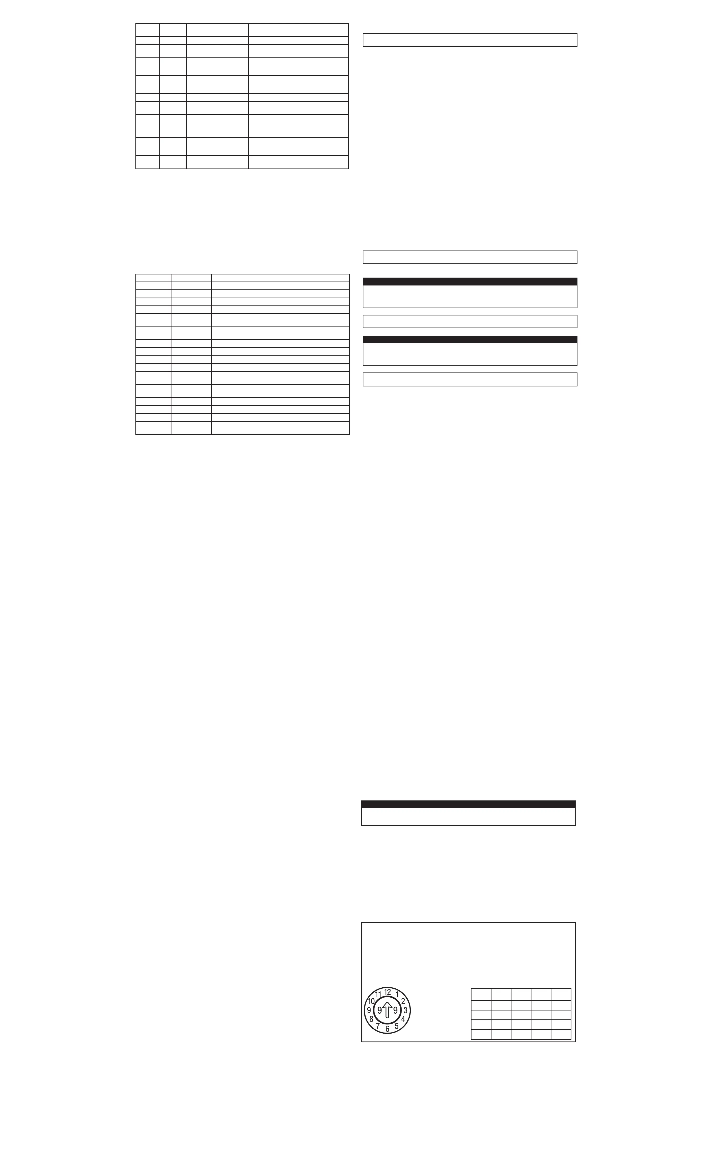
Product Manufacturing Date
The parts of the product show markings that bring information of manufacturing date, and its reading is described
as in the example below:
Date Code = 12th month 1999 (12/99) Date Code = First Quarter 2002
02 03 04 05 06
•
 Loading...