14
3.6 INSTALLING A HARNESS-MOUNTED SRD: Harness-mounted SRDs are secured directly to harnesses by means of a
harness interface. Harness interfaces are a type of connector specially designed for this purpose. In general, there are
two types of harness interface: straight-pin and carabiner. Instructions for each style are provided below.
;
Instructions may vary per harness interface model. For more information on how to use your harness interface, see
the manufacturer instructions for the harness interface or for the product it was provided with.
;
Do not remove the backplate from the harness when installing a harness-mounted SRD.
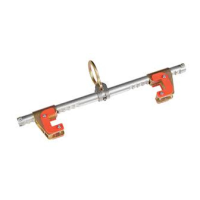
A. STRAIGHT-PIN INTERFACE: Straight-pin harness interfaces include a locking pin for securing to the harness.
Straight-pin interfaces may be used with Single-SRD or Twin-SRD formats, depending on the harness interface used.
See Figure 10 for reference.
1. Press both Locking Buttons (A) on the front of your harness interface to open. With the Locking Buttons held
down, remove the Locking Pin (B) from the harness interface.
2. Thread the Locking Pin (B) behind both Harness Straps (C), capturing the straps as you reinsert the pin into the
harness interface. An audible click should be heard when the Locking Pins are reengaged.
3. Verify that the harness interface is secure and that both Harness Straps (C) are captured by the harness interface.
B. CARABINER INTERFACE: Carabiner interfaces are carabiners that function as harness interfaces. Carabiner
interfaces may be used with Single-SRD or Twin-SRD formats, although methods will vary slightly. See Figure 11 for
reference, which shows how to install the carabiner interface using a Twin-SRD format.
1. Open the Gate (A) of the carabiner interface. Slide the SRD (C) over the open Arm (B) of the carabiner. Then,
slide the SRD to the opposite side of the carabiner.
2. Hold the Gate (A) of the carabiner interface open, then slide the open Arm (B) behind and around both Harness
Straps (D), capturing the straps within the carabiner interface.
3. Thread the second SRD (E) onto the open Arm (B) of the carabiner interface. Then, release the Gate to close and
secure the carabiner interface.
4. Verify that the carabiner interface is secure and that both Harness Straps (D) are captured by the interface.
;
For Single-SRD formats, only one SRD should be attached to the carabiner interface. In this format, the
carabiner interface may be secured as outlined above, or directly to your Dorsal D-ring instead. If securing to your
Dorsal D-ring, do not capture the harness straps.
Certain harness models covered in these instructions include additional features for securing harness-mounted SRDs. See
below for how these features should be used:
• SRD LOOP: Some Full Body Harnesses are equipped with an SRD Loop that integrates the Dorsal D-Ring with
attachment elements for Harness-Mounted Self-Retracting Devices (SRDs). Figure 12 illustrates attachment of
common SRD congurations: (A) Nano-Lok™ Edge SRDs, (B) Twin Nano-Lok™ SRDs, (C) Single Nano-Lok™ SRDs,
(D) Rebel™ SRDs. Other manufacturers’ SRDs can also be mounted on the harness in similar fashion. See the
manufacturer instructions for your SRD for more information.
;
Contact 3M Tech Services with any questions regarding compatibility of your SRD with the SRD Loop.
3.7 DEPLOYING THE SUSPENSION TRAUMA STRAPS: Figure 13 illustrates deployment of the Suspension Trauma Straps.
In the event of a fall, the Suspension Trauma Straps should be used by the fallen worker to alleviate suspension trauma.
To deploy the Suspension Trauma Straps on your harness:
1. Locate the Suspension Trauma Straps (A) on your harness. The Suspension Trauma Straps should be located in a
zipped container on your front, near the two intersection points of the leg straps.
2. Deploy the Suspension Trauma Straps by opening the zipped compartments located on the containers’ sides. Guide
the Straps (B) out from within each container to a length long enough for you to stand upon. Bring the two Straps
together and secure them to each other by means of the Strap Hook (C).
3. Extend the connected Straps as necessary to create a length of webbing for you to stand upon. Press your heels upon
either side of the connection point and stand up straight. This should transfer a signicant amount of weight to the
user’s feet, diminishing the likelihood of suspension trauma.
3.9 SECURING LANYARDS WITH LOOP ENDS: Some lanyards are designed to choke onto a web loop to provide a
compatible connection. Lanyards may be sewn directly to the web loop forming a permanent connection. Do not make
multiple connections onto one web loop, unless choking two lanyards onto a properly sized web loop. See Figure 9 for
reference. To choke a lanyard onto a web loop:
1. Insert the lanyard web loop through the web loop or D-Ring on the harness.
2. Insert the appropriate end of the lanyard through the lanyard web loop.
3. Pull the lanyard through the connecting web loop to secure.
3.10 CONNECTING SYSTEM COMPONENTS: After donning the harness, the user may connect to their Fall Protection
System. Observe all requirements as specied in these instructions and any manufacturer’s instructions included with the
system components. See the Product Overview for more information on System Applications.
 Loading...