Do you have a question about the 3M Protecta AC202C-SA2 and is the answer not in the manual?
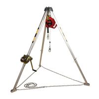
Lifeline Subsystems for Fall Arrest or Restraint systems, using synthetic or wire rope.
Conforms to national/regional standards; reseller must provide instructions in local language.
Equipment use must be supervised by a Competent Person.
Users must be trained in correct application, care, and use, aware of limitations and consequences.
Employer must have a written rescue plan with means to implement it, and trained personnel.
Sufficient Fall Clearance (FC) needed to arrest fall before striking ground or obstruction.
Minimize swing falls by working directly below anchorage; user work radius increases fall distance.
Remove from service immediately after fall arrest/impact force; tag 'DO NOT USE'.
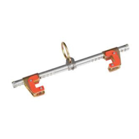
Anchorage requirements vary by application; mounting structure must meet specifications.
System must observe all Free Fall requirements defined in Table 1 per application.
System capacity limited by lowest rated component; comply with subsystem capacity requirements.
Use with environmental hazards may require additional precautions.
Avoid contact with sharp edges and abrasive surfaces; cover if contact is unavoidable.
Use only 3M-approved components; non-approved may jeopardize safety and reliability.
Connectors must be compatible in size, shape, strength; ensure self-locking and gate mechanisms.
Ensure self-locking connectors are compatible, fully closed and locked. Avoid improper connections.
Plan Fall Protection system, accounting for all safety factors before, during, and after a fall.
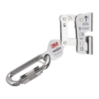
Install Rope Grab on vertical lifelines meeting Table 1 requirements; follow steps in Figure 9.
Activate/deactivate parking feature using Auto-Locking Lever as shown in Figure 10.
Verify work area, system, and rescue plan. Inspect product; remove if defective.
Use Rope Grab with Full Body Harness and Energy-Absorbing Lanyard; see Figure 8.
Inspect before each use; Competent Person inspects annually or more often if needed.
Follow 'Inspection and Maintenance Log' procedures; maintain documentation.
Remove defective products from service; destroy or send for repair to 3M authorized center.
Functional life determined by work conditions and maintenance; pass inspection to remain in service.
Clean Rope Grab with soap/water; clean lanyard webbing; allow to air dry.
Only 3M or authorized parties may make repairs to equipment.
Store/transport in cool, dry, clean environment away from sunlight and chemicals.
Markings must be present and legible; replace if not. See Figure 12 for details.
Markings must be present and legible; replace if not. See Figure 12 for details.
| Brand | 3M |
|---|---|
| Model | Protecta AC202C-SA2 |
| Category | Safety Equipment |
| Language | English |