S
A
S
A
S
A
S
M
AX
A
F
M
IN
A
F
A
EQ
L
EQ
L
Settings
Frequency weighting and time response
The frequency weighting and the time response can be changed on the instrument by pressing the
following when in stop mode.
1. To change A or C frequency weighting, press the A/C key.
2. To change Fast or Slow time response, press the F/S key.
Exchange rate (ER)
The exchange rate can be set to either 3 dB (for LEQ values) or 5 dB (for LAVG values).
The factory default is set at 3 dB. To change press the following when switched off.
1. Press and hold the F/S key and then press the power key.
2. The E.r. screen will appear. Press F/S key to change the setting.
3. Press the mode key to accept the setting (to cancel, press the power key).
Running and Stopping a study
The run/stop key is used to start and stop the Run-Time for integrating measurements which include
LEQ/LAVG, Optime alert and HP, MAX and MIN screens.
1. When switched on, press the Run/Stop key. The ► icon appears. NOTE: Whilst in run mode, the
settings cannot be changed (see Settings for more information).
2. To stop, press the run/stop key. The ► icon disappears.
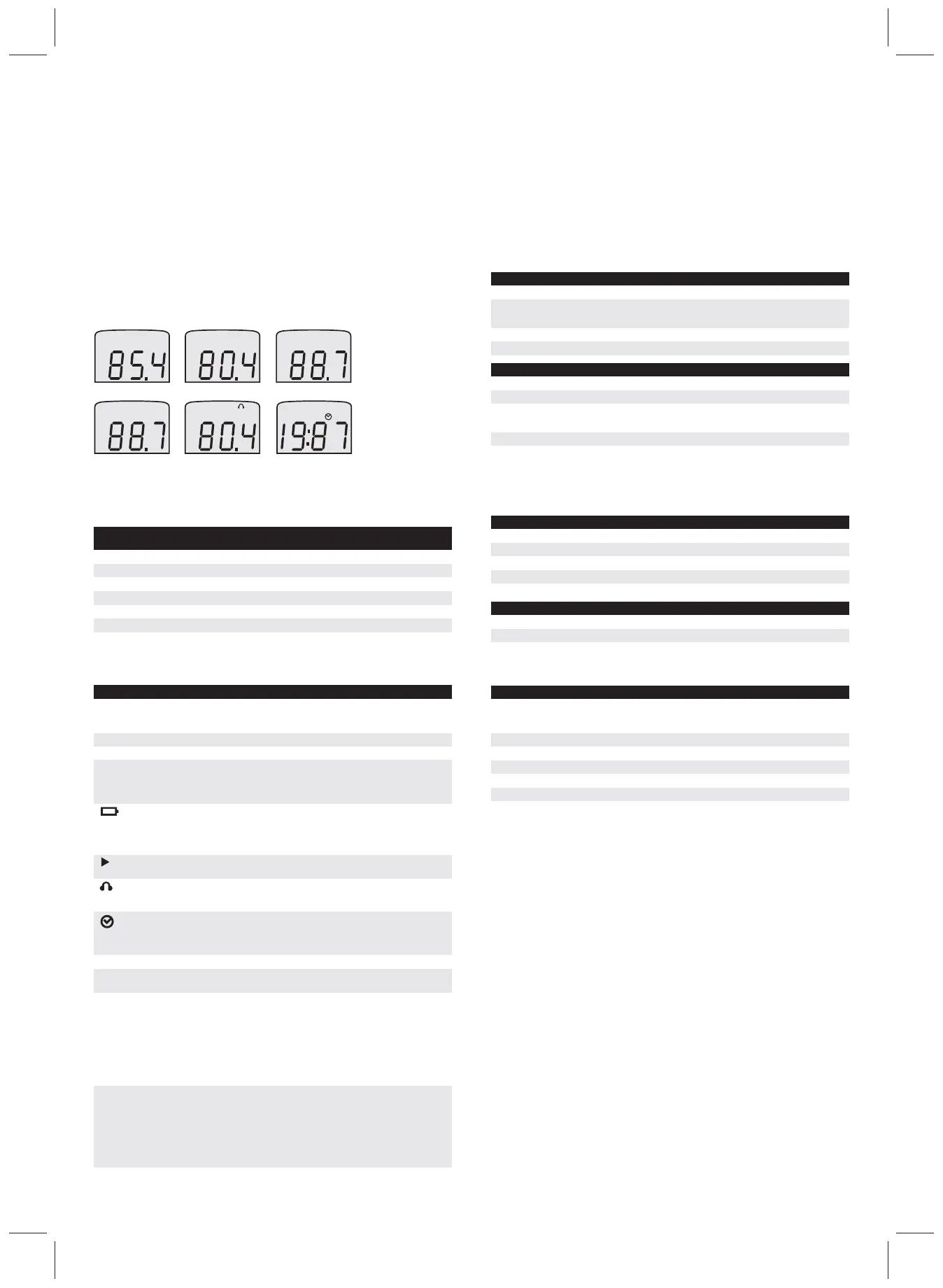
Viewing Measurements
The mode key is used to cycle through the measurement screens with its related values.
There are six measurement screens (See figure 3):
3M™ Optime™ Alert and Hearing Protection (HP) screen
The Optime Alert and hearing protection (HP) screen displays LEQ/LAVG measurements, a HP
icon and activated LED with specific indicator levels (See Table 1).
The LED levels can be used to help select the appropriate hearing protection when measured
with A frequency weighting.
Environmental Effects
The typical time intervals needed to stabilize after changes in environmental conditions include:
• For temperature change of 10°C (18°F) allow at least 5 minutes.
• For relative humidity change of 30% (non-condensing) allow at least 30 minutes.
• For static pressure changes of 10kPa allow at least 5 seconds.
Keypad
• 5 keys: F/S key, A/C key, Mode key, Run/Stop Key, Power On/Off Key
Special functions
LED's: light-emitting diodes are activated in the Optime Alert LED (HP) measurement screen. They
will flash at the levels indicated below. (Note: these are set at the "E" country code levels.)
• Green LED flashes when noise measurements are 80 to 85 dB(A).
• Yellow LED flashes when noise measurements are 83 to 93 dB(A).
• Red LED single slow flashes when noise measurements are 87 to 95 dB(A).
• Red LED double flashes when noise measurements are above 95 dB(A).
Product Information
• Sound detector kit, USB Cable, Windscreen (3M ID: 70-0715-6546-2)
Accessories
• Windscreen (1 included) (3M ID: 70-0716-0639-9)
• Mini-USB cable (1 included) (3M ID: 70-0715-8175-8)
• 056-990 0.5" Calibrator adaptor (3M ID: 70-0715-8115-4)
• Calibrator: QC-10: 114dB at 1kHz output (3M ID: 70-0715-7972-9)
• Tripod (3M ID: 70-0715-8374-7)
Updates
In the interest of continuous product improvement, 3M reserves the right to make changes to product
specification without notice.
To understand the latest updates that have been implemented into this product and to download the
most current version of this user manual, visit the 3M website: www.3M.com/OccSafety
Warranty
3M™ Sound Detector SD-200 LIMITED WARRANTY. 3M™ warrants the Sound Detector SD-200
will be free from defective materials and workmanship for one year from date of purchase (indicated
on the sales receipt), provided it is maintained and used in accordance with 3M instructions and/or
recommendations. If any component becomes defective during the warranty period, it will be
replaced or repaired free of charge.
This warranty does not apply to units that have been altered or had repair attempted, or that have
been subjected to abuse, accidental or otherwise.
The above warranty is in lieu of all other express warranties, obligations or liabilities.
THE IMPLIED WARRANTIES OF MERCHANTABILITY AND FITNESS FOR PARTICULAR
PURPOSE ARE LIMITED TO ONE YEAR FROM THE PURCHASE DATE.
3M shall not be liable for any other warranty, express or implied, arising out of or related to the
appropriate use of hearing protection devices. Manufacturer or its agent's liability shall be limited to
replacement or repair as set forth above.
Buyer's sole and exclusive remedies are return of the goods and repayment of the price, or repair
and replacement of defective goods or parts.
Measurement Screen Indicators
Measurement Screen Indicators are a type of notification identifying measurement parameters
and screen icons.
Optime Alert and hearing protection indicator levels
(NOTE: Suggested HP may be used on LED indicator levels)
1. SPL (No measurement
screen indicator);
2. LEQ/LAVG*; 3. MAX*;
4. MIN*; 6. Run-time*5. Optime alert and HP*; and
*When integrating
measurement has
occurred.
Figure 3.
Green LED
Green and Yellow LEDs
Yellow LED
Housing
Size (Length x Width x
Thickness)
Weight
Tripod Mount
ABS/Polycarbonate
Operating Temperature 0°C-40°C (32°F-104°F)
Operating atmospheric pressure 80-110kPa
Relative Humidity >90%, non-condensing
Storage Temperature -20°C-70°C (-4°F-158°F)
Storage atmospheric pressure 50-150kPa
Display Data and Status Indicators Sound Pressure Level (SPL), Average Value (LEQ/LAVG), Optime alert
and HP, Maximum value (MAX), Minimum value (MIN) Run-Time (max 99
hours), Overload (OL) and Under-Range (UR)
Digit size 2cm
Resolution 0.1dB
Display Range 40 to 130 dB (Dynamic range)
Linearity Range 45 to 130 dB (Dynamic range)
Frequency Weighting A or C
Time Response Fast (125 msec) or Slow (1 sec)
Exchange rate (ER) 3 dB or 5 dB
Calibrator Calibration should be performed at 114dB at 1kHz
Update Rate 0.5sec
Battery Type
Lithium polymer battery (1000mAh), rechargeable
Battery Life
3 years or 500 charge cycles
Battery run-time
35 hours with LEDs activated (minimum hours, 40 hours typical) 50+
hours without LEDs Activated
Microphone
Omni-directional; Class/Type 2; ½" diameter; electret condenser
Frequency Range
31.5 to 8000 Hz
16.5cm x 6.1cm x 2.3cm
6.5" x 2.4" x 0.9"
125g (4.4oz)
Accepts a ¼" – 20 screw (located on bottom, backside of the instrument).
Yellow and Red LEDs
Red LED
Red LED
Flashes when noise measurements are 80-85dB(A)
Flashes when noise measurements are 83-85 dB(A)
Flashes when noise measurements are 83-93 dB(A)
Flashes when noise measurements are 87-93 dB(A)
Flashes single slow pulses when noise measurements are 87-95 dB(A)
Double Flashes when noise measurements are >95 dB(A)
Table 1.
Table 2.
Indicator
Mechanical Characteristics
Electrical Characteristics
Temperature Ranges.
Measurements
User Interface Display
Definition
SPL
MAX
MIN
OL
UR
A/C
F/S
LEQ/LAVG
Battery Power
Run
Hearing Protection
Run-Time
Sound pressure level - The basic measure of noise loudness expressed in
decibels. SPL uses the ratio between a reference level of 20 microPascals (.00002
Pascals) and the level being measured. It is displayed in decibels (dB).
Maximum sound level - The highest SPL measured during integrating period.
Run indicator - Signifies that you are measuring LEQ/LAVG, Optime alert and HP,
MAX, and MIN screens over the Run-Time.
Under Range – Indicates that the displayed measurement is below the linearity
range.
Hearing protection icon – Appears when viewing the Optime alert and HP screen.
(Note: LEDs will flash if set points are met or exceeded and while in run mode.
See "Optime alert and HP screen" for more info.)
Run-Time – Indicates the time elapsed from the start of the run mode which is
used to calculate the LEQ/LAVG, Optime alert and HP , MAX, and MIN values.
Run-Time computes in seconds, minutes, and hours. (Displayed as: (1)
Minutes:seconds (2) Hours:minutes, and (3) Hours changing at 19:59.)
Fast/Slow time response - The response time setting determines how quickly the
unit responds to fluctuating noise. Typically, noise is not constant. If you were to try
to read the sound level without a response time, the readings would fluctuate so
much that determining the actual level would be extremely difficult. Using a
response of slow or fast smoothes the noise fluctuation and makes the sound level
easier to work with. While the terms slow and fast have very specific meanings
(time constraints), they work very much as you would expect. The fast response
would result in a more fluctuating sound level reading than would the slow
response. (See Specifications, "Time Response")
A frequency weighting or C frequency weighting - These are frequency filters that
cover the frequency range of human hearing (20 Hz to 20 kHz). "A" weighting is a
commonly used filter in both industrial noise applications and community noise
regulations. The "A" weighted filter makes the sound level meter respond closer to
the way the human ear hears. It attenuates the low frequency noise below several
hundred Hertz as well as the high frequency above six thousand Hertz. "C"
frequency weighting is intended to represent how the ear perceives sound at high
decibel levels.
Minimum sound level - The lowest SPL measured during integrating period.
Overload – Indicates that the dB has exceeded the range of SD-200.
There are two battery indicator states
When battery power icon appears, this indicates the instrument has low power and
needs to be charged.
Battery power icon flashing indicates the battery is charging.
Equivalent pressure sound level/Average sound pressure level – The true
equivalent sound level (or average SPL) measured over the integrating period.
The term LEQ is used when 3 dB exchange rate is applied; The LAVG is used
when 5 dB exchange rate is applied.
Troubleshooting
In the event that your SD-200 locks up for an unknown reason, the SD-200 is equipped with a reset
feature. To reset the instrument, press and hold the power key for at least 20 seconds and then release
the key. The instrument will power back on.NOTE: After a reset, LEQ/LAVG, Optime Alert and HP, MAX
and MIN measurement screens will display dashes "--.-" and Run-Time will display zero "0:00".
Please contact 3M or your supplier for additional support.
SPECIFICATIONS
Standards/Directives
• ANSI S1.4 1983 (R 2006) – Type 2/ Specification for Sound Level Meters
• ANSI S1.43 1997(R 2007) – Type 2/ Integrating-Averaging Sound Level Meter
• IEC 61672-1 (2002-2005) - Class 2/ Electro Acoustics – SLMS – Pt1: Specifications
• IEC 61010-1 (2001-2002) – Safety requirements for electrical equipment for measurement, control &
laboratory use part 1: requirement
• 2004/108/EC Electromagnetic Compatibility (EMC)
• 2006/95/EC Low Voltage Equipment (LVD) Safety
• 2002/95/EC Restriction of Hazardous Substances (RoHS)
• 2002/96/EC Waste Electrical and Electronic Equipment (WEEE)
• CE mark
2

 Loading...