11
ENGLISH
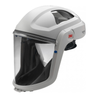
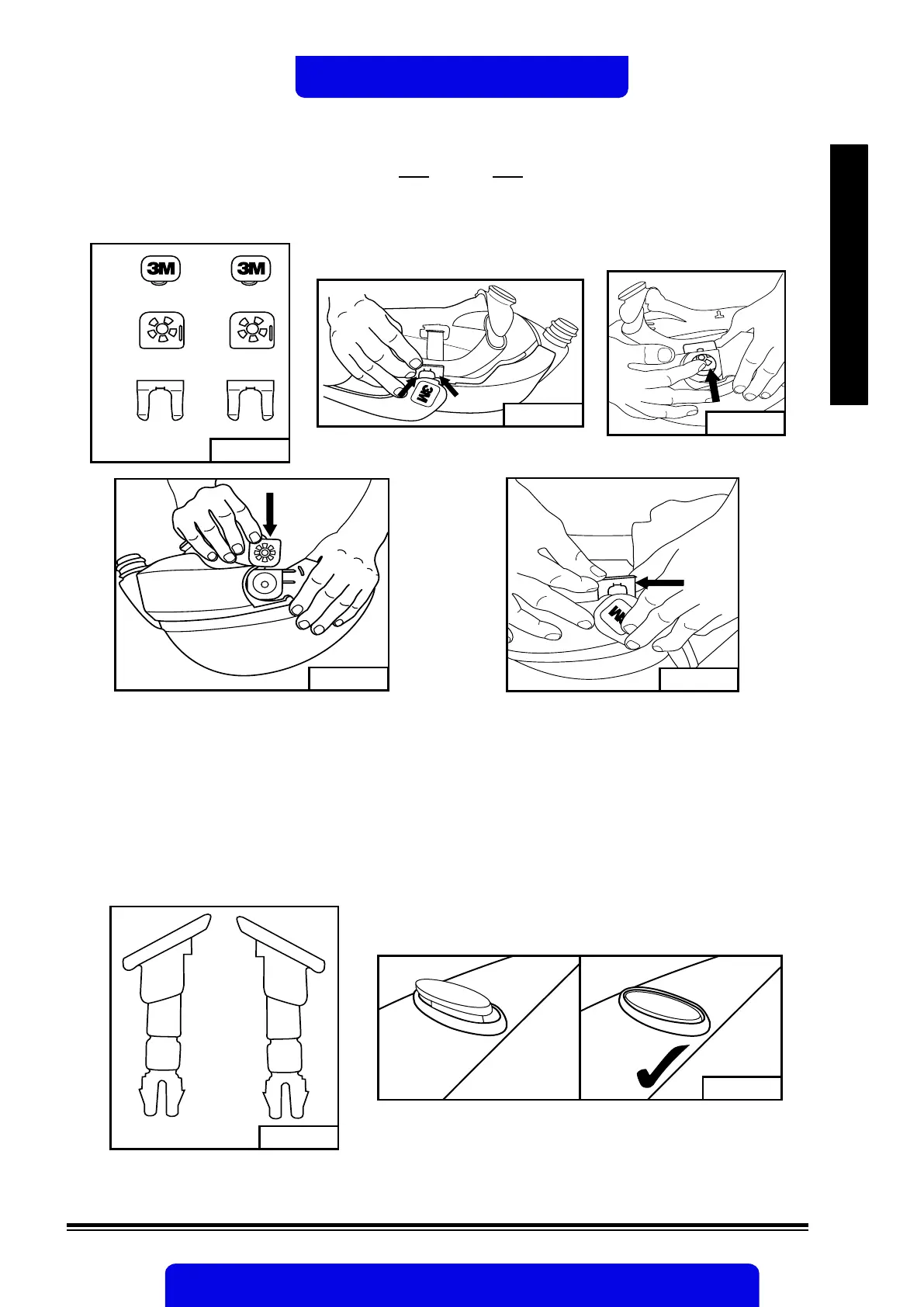
- Line up visor frame over attachment slots and slide spring into place. With the post and back plate
engaged, the visor frame should be in the fully open or fully closed position before the spring is
installed (Fig. 6e).
- Verify the visor frame and pivot kit is correctly installed by raising and lowering the visor several
times. Ensure the visor stays rmly in the up (open) and down (closed) positions.
Fig. 6a
1
2
3
Fig. 6b
Fig. 6c
Fig. 6d
Fig. 6e
M-919 Visor Frame Buttons
The visor frame buttons are designed to stay slotted in the visor frame until broken, worn or damaged. To
replace broken or worn buttons, move the visor frame to the up (open) position. Remove visor from frame
as described in the previous section. Remove worn or broken button(s). Gently use a tool if necessary
(e.g. pliers) to assist in removal. Install new buttons one at a time, ensuring they are correctly aligned on
each side of the frame. Fig. 7a shows how the buttons should be positioned (i.e. sloped at tops are both
pointed in towards each other and not outwards on the frame). Re-install visor and ensure visor buttons
are rmly secured and ush to the visor frame (Fig. 7b). If the buttons do not seat ush to frame, check
that they were correctly installed.
Reinstall if necessary.
Fig. 7a
 Loading...