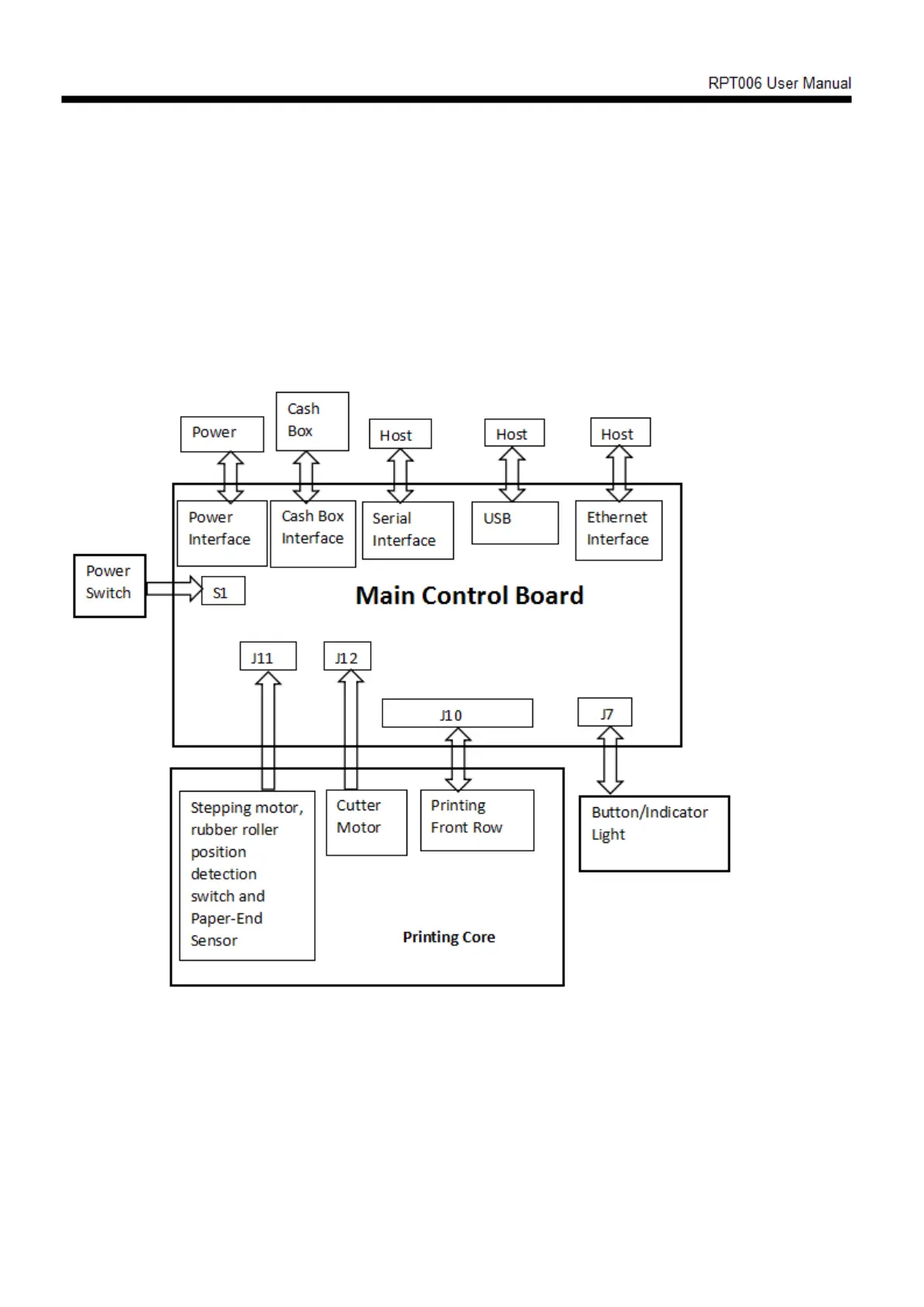
2.2 Connection diagram of control board components
The main control board, printing engine, cutter, keys, etc. are adopted for the printer to
connect to the main control board through the connector or transfer board. The following is
the connection diagram of the serial port +USB+ network port control board components:
2.2.1 Connection diagram of serial port +USB+ network port control board
 Loading...