510 Indoor / 510 Outdoor Service Manual
Ver. 1.00
12
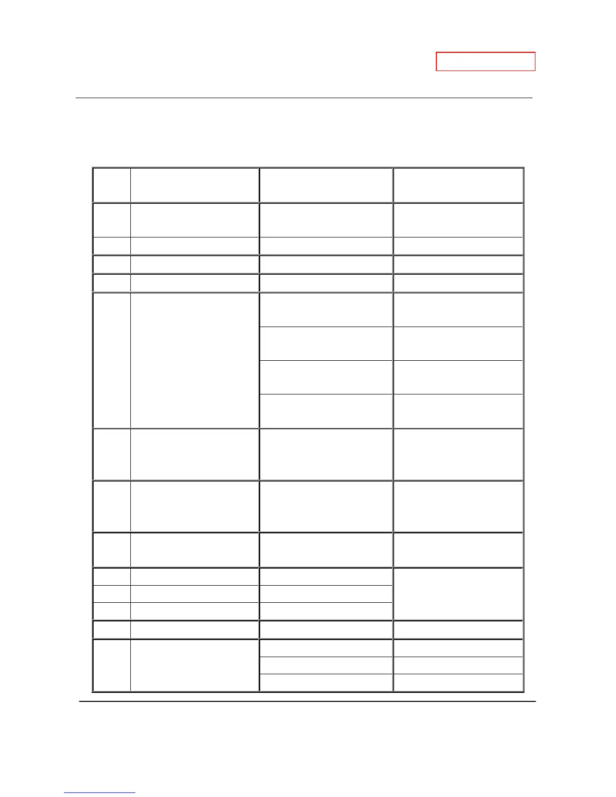
7. Wiring diagram check points for diagnosis
The table below applies to both the 510 Indoor and 510 Outdoor.
Check-
Part and Description Color of wires Normal range
A, A1
100V Power supply
White – Black (A)
Brown – Brown (A1)
90 to 110 VAC
A2, A3
120V Power supply Black - White 108 to 132 VAC
B Igniter Purple - Purple 90 to 110 VAC
B1 Heater Black - Black 90 to 110 VAC
C Gas valves
Light blue - blue at COM (MV)
78 to 100 VDC (during
operation) / 0.9 to 1.3 kΩ
Green - blue at COM (SV1)
78 to 100 VDC (during
operation) / 1.3 to 1.9 kΩ
Orange - blue at COM (SV2)
78 to 100 VDC (during
operation) / 1.3 to 1.9 kΩ
Red - blue at COM (SV3)
78 to 100 VDC (during
operation) / 0.9 to 1.7 kΩ
C1 Hi-limit switch Blue - Blue
Less than 1 VDC
and
less than 1.0 Ω
C2 Overheat cutoff fuse Blue - Blue
Less than 1 VDC
and
less than 1.0 Ω
D1,D2
Easy-link connectors Black - White
15 VDC
(during Easy-link operation)
E1 Mixing thermistor Black - Black
See table on p. 11 E2 Output thermistor Black - Black
E3 Inlet thermistor Black - Black
F Remote controller * 11 to 25 VDC
G Fan motor
Red - Blue 110 to 160 VDC
Yellow - Blue 13 to 17 VDC
Orange - Blue 2 to 6.5 VDC
 Loading...