EasyManua.ls Logo

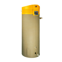
A.O. Smith BTR 120-400 User Manual

A.O. Smith BTR 120-400
31 pages
To Next Page IconTo Next Page
Page #1 background imageLoading...
Page #1 background image
COMMERCIAL GAS HIGH EFFICIENCY WATER HEATERS
Service Handbook
PRINTED IN THE U.S.A. 1016 100277701_2000536453_Rev A
500 Tennessee Waltz Parkway
Ashland City, TN 37015
FOR MODELS:
BTR 120 thru 400(A) Series 118 & 119
INSTALLATION CONSIDERATIONS - PRE SERVICE CHECKS -
CONSTRUCTION - OPERATION & SERVICE - TROUBLESHOOTING
SERVICING SHOULD ONLY BE PERFORMED BY A QUALIFIED SERVICE TECHNICIAN

Questions and Answers:

A.O. Smith BTR 120-400 Specifications

General IconGeneral
BrandA.O. Smith
ModelBTR 120-400
CategoryWater Heater
LanguageEnglish

Summary

INTRODUCTION

QUALIFICATIONS

Required skills and expertise for installation and service personnel.

SERVICE WARNING

Crucial advisory against non-qualified service personnel performing tasks.

SERVICE REMINDER

Advice on performing troubleshooting steps carefully and inspecting connections.

TOOLS RECOMMENDED

List of essential tools required for servicing the water heater.

INSTALLATION CONSIDERATIONS

INSTRUCTION MANUAL

Reference to the primary installation guide for comprehensive instructions.

CLOSED WATER SYSTEMS

Discussion of implications for water systems configured as closed loops.

THERMAL EXPANSION

Explanation of water expansion upon heating and its potential effects.

AIR REQUIREMENTS

Importance of adequate combustion and ventilation air for safety and performance.

CONTAMINATED AIR

Impact of air quality on heater components and lifespan.

VENTING

POWER VENT KITS FOR SIDEWALL VENTING

Information regarding the use and installation of sidewall power vent kits.

GAS SUPPLY SYSTEMS

SUPPLY GAS REGULATOR

Guidelines for selecting and installing gas pressure regulators.

GAS PIPING

GAS PIPING AND SEDIMENT TRAP INSTALLATION

Details on gas line setup, including sediment trap installation.

PURGING

Procedure for safely removing air from gas supply lines.

FEATURES AND COMPONENTS

THE ELIMINATOR (SELF-CLEANING SYSTEM)

Explanation of the self-cleaning feature for water inlet.

AUTOMATIC FLUE DAMPER

Description of the component that reduces heat loss during off cycles.

UNCRATING

Initial steps for unpacking and preparing the water heater.

GAS CONTROL VALVE

GAS PRESSURE SPECIFICATIONS

Required gas pressures for natural and propane operation.

WHITE RODGERS INTEGRATED TEMPERATURE CONTROL-HIGH LIMIT SWITCH

STATUS LEDS

Explanation of the indicator lights on the control unit.

ELECTRONIC IGNITION CONTROL/IGNITION MODULE

SEQUENCE OF OPERATION FLOW CHART

TROUBLESHOOTING CHECKLIST

GENERAL SERVICE CHART

FAULT AND WARNING CODES - CONTINUED

STEP 1. TROUBLESHOOTING THE BTR WATER HEATERS

Initial step in diagnosing issues with BTR water heaters.

EFFIKAL DAMPER

Specific troubleshooting information for the Effikal damper component.

EFFIKAL RVGP-KSF-SERIES FLUE DAMPER TROUBLESHOOTING GUIDE

STEP 2: TEST FOR 24VAC BETWEEN BLACK AND ORANGE ON DAMPER PC BOARD

Diagnostic test for voltage on the damper PC board.

STEP 3: TEST THE THREE AMP FUSE

Procedure to check the integrity and function of the main fuse.

STEP 4: TEST FOR 24VAC BETWEEN BLACK AND YELLOW ON DAMPER PC BOARD

Diagnostic test for specific voltage points on the damper PC board.

STEP 5: WIRE HARNESS TEST

Checks continuity and connections within the wire harness system.

STEP 6: IID MODULE TEST (POWER TO THE PILOT VALVE)

Tests the ignition module's output to the pilot valve.

STEP 7: PILOT SPARK TEST

Verifies that the pilot assembly is generating a spark.

STEP 8: FLAME RECTIFICATION

Checks for proper pilot flame sensing by the ignition module.

STEP 9: IID MODULE TEST

Further diagnostic tests for the Ignition Interruption Device (IID) module.

STEP 10: MAIN BURNER TEST

Confirms proper ignition and operation of the main burner.

WIRING DIAGRAM - BTR 118/119 SERIES

WIRING DIAGRAM - BTR 118/119 SERIES CONTROLS

NOTES

Related product manuals