39
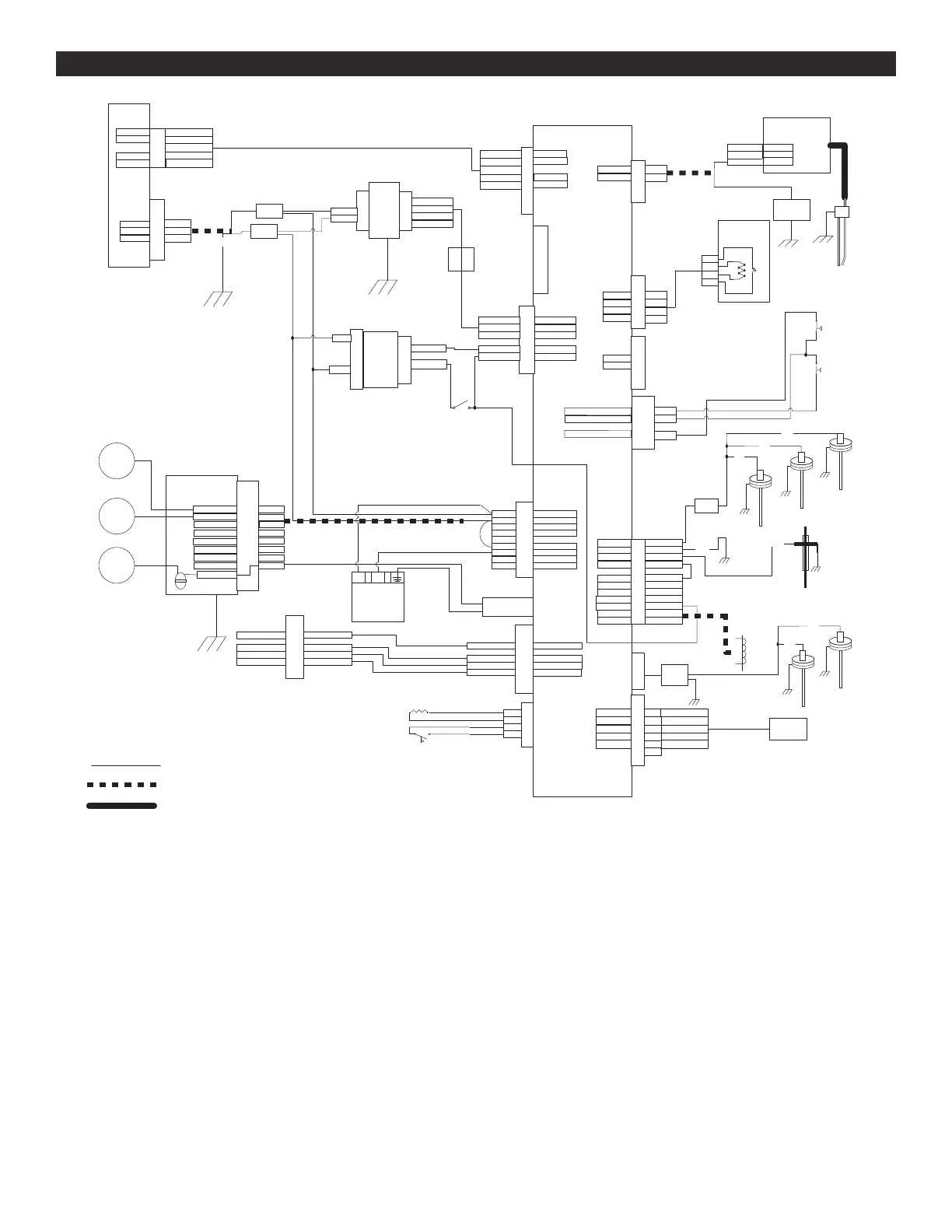
WIRING DIAGRAMWIRING DIAGRAM
Splice
Splice
Green
Green
Ferrite
Bead
Tr
ansformer
Secondary
White / Red
White / Blue
Transformer
Primary
Black
White
Transformer
Power
Supply J2
1 Blue
3 Orange
4 White/Green
Power
Supply J1
2 White
3 Black
75VA
Power
Supply
Central Control Board
(CCB)
Blower
1 Black
2 White
3 Green
120V OUT to blower
L1
Neutral
PE
1 White / Brown
2 White / Orange
4 White / Blue
Blower
Speed
5 White / Green
24Vureg
PWM Signal
Speed f-back
Dgnd
8 White
Field Box
HIGH Voltage
J1
7 Black
6 Red
5 Green
Green
Neutral
L1
Aux 2 Common
Aux 2 NO
Open
Open
Open
Open
PE
Junction Box
CCB
J16
Low Voltage In
1 White/Red
2 White/Blue
4 Blue
5 Orange
6 White/Green
24VAC
24VAC
12VDC
5VDC
Dgnd
9 White
CCB J1
HIGH Voltage In
8 Black
7 Red
6 Green
3 Black
4 White
5
2 Red
1
Neutral
L1
Pump Common
Pump NO
AUX NO
AUX Common
AUX NC
PE
CCB J5
Blo
wer Logic
1 White/Brown
2 White/Blue
4 White/Orange
5 White/Green
24Vureg
PWM Signal
Speed f-back
Dgnd
Green
Yellow
CCB J14
Limit String
1 Blue
2 Green
3 Yellow
4 Black
6 Black
7 Red
8 Black
9 Red
10 Black
11 Red
12 Black
Anode
Dgnd
Flame Rod
Condensate
Gas PS
Gas V Switch
Gas V 24V
24V Rtn
Condensate
Gas PS
Gas V Switch
1 Red
2 Black
CCB J6
120V Out
Neutral
120 to Spark
Red
Black
Red
Black
Upper Temperature
Probe / ECO
1 Red
2 Black
CCB J9
Upper Probe
ECO
Thermistor
4 Red
3 Black
ECO
Thermistor
Gas Valve
Ground Bar
N
L
Heater
Pump
Neutral
Protective
Earth
= multi-conductor power limited cable, 18AWG 80°C 300V UL category QPTZ
Connects
to burner
bolt
= Spark ignition wire, 220°C 25kVDC 7mm EMI suppression
Flame
Rod
CCB J17
Low Voltage Field
No factory
connections
Enable/Disable Switch
CCB J10
Thermistor
Thermistor
Splice
Blue
Blue
P1-1
W1-Red
P1-2
W2-Green
P1-3
W3-White/Brown
P1-4
W4-White/Blue
CCB J12
Configuration Key
SDA (data)
SCL (data)
Write protect
P1-5
P1-6
W5-White/Orange
+5V
Dgnd
Configuration
Key
Outlet Pressure
Switch
1 Black
2 Red
CCB J15
Pressure
Switches
Inlet return
Outlet return / Inlet power
4 Green
Outlet power
Inlet Pressure
Switch
= 18AWG AWM wire 105°C 600V UL style 1015. Flame rod wire = 200°C 300V UL 1180.
Spark
Module
120V
Neutral
Spark
Rod
1 Red
2 Black
3 Green
Ground
BURNER
BOLT
L1
+5V
Data +
Data -
D gnd
1 Blue
3 Yellow
4 Orange
5 Violet
1 Blue
3 Yellow
4 Orange
5 Violet
Display J1
CCB J3
+5V
Data +
Data -
D gnd
Top
Anode
Rod
Blue
CCB J13
CPAM
Anode
Side
Side
Rod
Anode
Rod
Blue
Blue
Top
Anode
Rod
Top
Anode
Rod
1 Black
2 Black
3 Red
4 Red
CCB J4
Flue Probe
Flow Switch
 Loading...