19
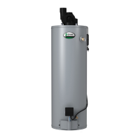
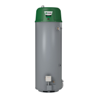
FIGURE 22
Apply hi-temp red silicone (included) around the collar on air
manifold box. Pull corrugated vent tube all the way on to collar
and secure with one sheet metal screw (approx. 3/4 in. up from
edge of vent tube. Pull gear clamp past screw and tighten.
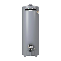
FIGURE 23
OFFSET VENT ARRANGEMENT
CONDITION 1:
Where a straight vent arrangement is impossible, a horizontal 90
degree maximum bend can be made. Use the water heater cas-
ing outer diameter as a template to form the corrugated tube.
TOP VIEW
90° MAXIMUM
BEND
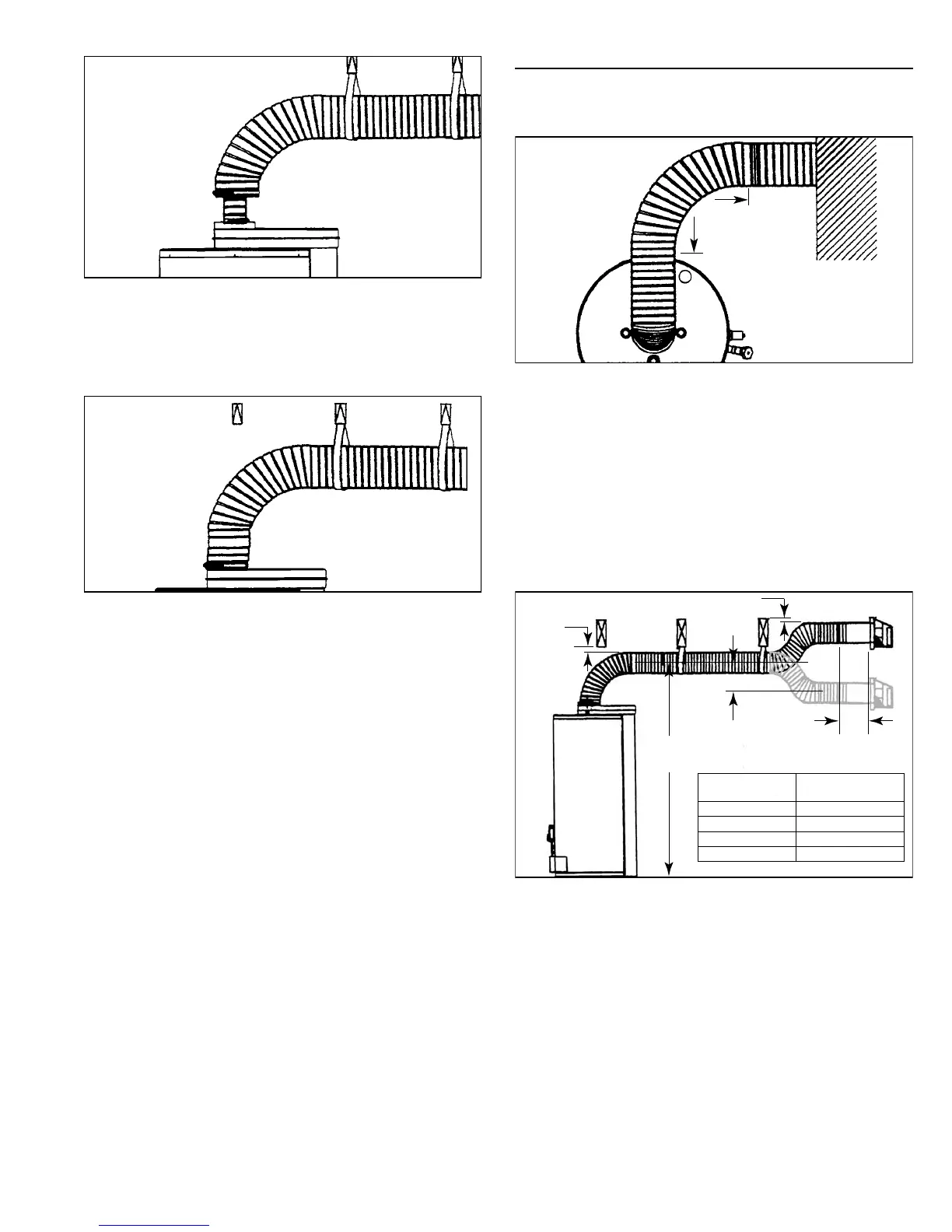
FIGURE 24
CONDITION 2:
Where fl oor joists impede venting, a rise or drop to complete
the vent termination is possible. All installations require 1 in.
clearance to combustibles.
NOTE:
A. The maximum horizontal vent length of 80 in. minus wall
thickness should be considered when installing an offset vent
arrangement.
B. Do not combine condition 1 (Figure 24) with condition 2
(Figure 25) in the same installation.
C. The maximum allowable drop from vent center-line to vent
termination center-line (Figure 25) is 7.25 in..
7.25 in.
MAX
“H”
SEE
CHART
WALL 10 in.
(REF)
>1 in.
>1 in.
MODELS
RECOMMENDED
MINIMUM “H”
40 gal. 68 in.
50 gal. 76 in.
50 gal. Hi-INPUT 76 in.)
75 gal. 76 in.
FIGURE 25