27
REMOVING THE BURNER FROM THE MANIFOLD/
BURNER ASSEMBLY
NATURAL GAS (LOW NOX) & L.P. GAS BURNER
Take off the burner by removing the two (2) screws located
underneath the burner.
Check the burner to see if it is dirty or clogged. The burner may
be cleaned with soap and hot water (Figure 24).Important: DO
NOT remove the orifi ce.
BURNER
(BOTTOM VIEW)
PILOT ASSEMBLY
(BOTTOM VIEW)
SCREWS
FIGURE 24
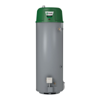
REPLACING THE PILOT/THERMOPILE ASSEMBLY
1. Remove the manifold door assembly as described in “Remov-
ing the Manifold/Burner Assembly” section.
2. Remove the burner to access the pilot/thermopile assembly.
Remove and keep the screws securing the burner to the mani-
fold (Figure 24).
Important: DO NOT remove the orifi ce.
3. Remove the screw securing the pilot/thermopile assembly to
the pilot bracket and keep for reuse later (Figure 25).
4. Lift the retainer clip straight up from the back of the manifold
component block (using a fl at-blade screwdriver), then remove
the manifold component block from the manifold door (Figure
25). Important: Be careful not to bend or alter the position of
the pilot tube. It will be used as a bending template for the new
pilot assembly. Note the placement/order of the wires in the
manifold component block.
5. Lift the pilot/thermopile assembly (including the igniter wire)
from the manifold assembly.
PILOT
TUBE
THERMOPILE
CONNECTOR
PILOT / THERMOPILE
ASSEMBLY SCREW
RETAINER
CLIP
WHITE
WIRE
MANIFOLD
COMPONENT
BLOCK
MANIFOLD
DOOR
BURNER AND OTHER
FITTINGS NOT SHOW
FOR CLARITY.
IGNITER
WIRE
FIGURE 25
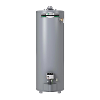
6. Read this step carefully before proceeding. Using the old
pilot/pilot tube assembly as a guide, bend the new pilot tube
to match the old one. Make only the bends closest to the pilot
before going to the next step.
1.
2.
PILOT/THERMOPILE
ASSEMBLY
WHITE
WIRE
THERMOPILE
CONNECTOR
THERMOPILE
PILOT
IGNITER
CONNECTOR
PILOT TUBE NOT
SHOWN FOR CLARITY
FIGURE 26
7. Route the new pilot tube, igniter wire and thermopile wire
through the opening in the manifold door. See Figure 25.
8. Using the pilot screw removed earlier, attach the
new pilot/thermopile assembly. Reattach the burn-
er to the manifold using the screws removed earlier.
Note: Make sure the burner scoop is oriented to the pilot side
of the manifold tube (Figure 24).
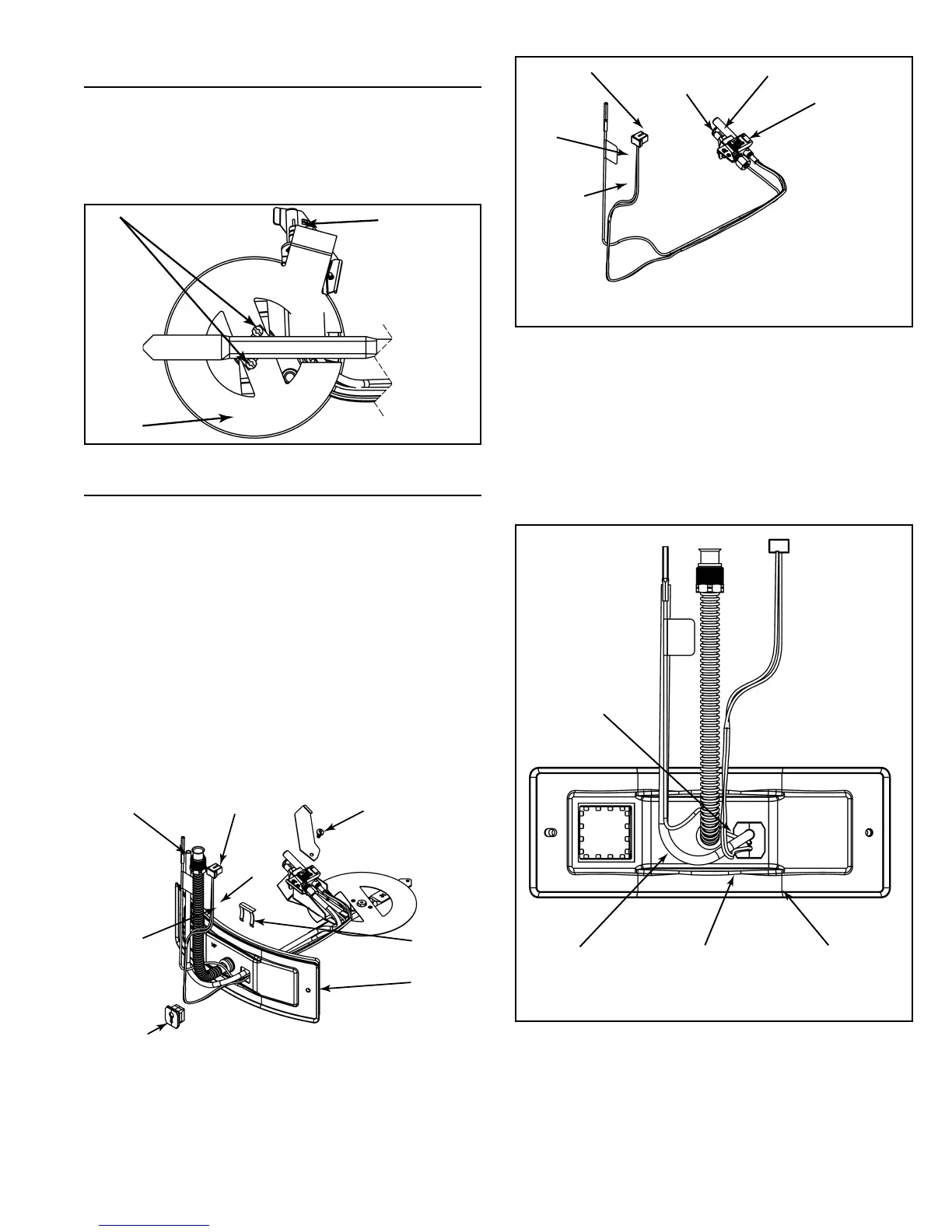
9. Reinstall the manifold component block in the manifold door.
Ensure that the pilot tube and wires are positioned as shown
in Figure 27.
THERMOPILE WIRES
PASS THROUGH
BOTTOM HOLE OF
MANIFOLD
COMPONENT BLOCK
PILOT TUBE PASSES
THROUGH TOP
HOLE OF MANIFOLD
COMPONENT BLOCK
(LARGEST HOLE)
IGNITER WIRE PASSES
THROUGH CENTER OF
MANIFOLD
COMPONENT BLOCK
(SMALLEST HOLE)
MANIFOLD
COMPONENT
BLOCK
FIGURE 27
10. Carefully bend the new pilot tube to match the bend of the
manifold tube.
Note: When bending, DO NOT crimp or crease the pilot tube.
11. Before you proceed to the next step, install the new brass fer-
rule nut in the gas control valve/thermostat’s pilot tube open-
ing, HAND TIGHT ONLY.
12. Install the manifold/burner assembly. Refer to the “Replacing
the Manifold/Burner Assembly” section for instructions.