
D
Darius LarsonOct 27, 2025
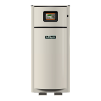
What to do if the UIM display is blank on A.O. Smith VF VB 1000?
- KKenneth MatthewsOct 27, 2025
If the UIM display on your A.O. Smith Boiler is blank, there are several potential causes. First, ensure the boiler is turned on by checking the on/off switch and replacing it if it's defective. Then, confirm that the 120 VAC power is properly connected in the junction box on the back of the boiler. Also, check for 24 VAC output at the transformer secondary winding terminals; if it's absent and the previous checks passed, replace the transformer. Inspect the 7.5 amp fuse on the MCB and replace it if blown or missing. Check the F3 transformer fuse on the PDB; if blown, inspect the wiring for shorts before replacing the fuse. Examine the communication ports on the MCB and UIM for damage or wear. Finally, check the communication cable connections at the UIM and the MCB's Internal Comm Ports, ...