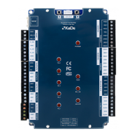
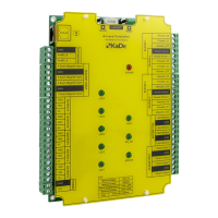
Integrated Access Controller – Installaon manual
All rights reserved. © AAT HOLDING S.A.
6
Installation and Wiring Diagram
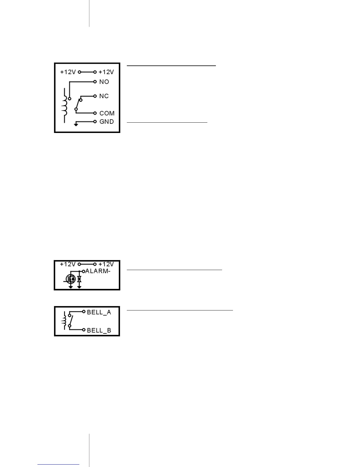
Principle of Electronic Lock
The relay will close contact to unlock the lock and will re-
lease after unlocking
COM: common, relay contact
NC: normal close, normally keep closed to COM
NO: normal open, normally keep opened to COM
Wiring of electronic lock
Connect COM and GND, connect two ends of electronic
lock with +12V and NO(or NC), complete the circuit.
Type A electronic lock: Fail Secure lock (Unlock when
power on), such as Electronic Controlling Lock, smart lock
etc.
Type B electronic lock: Fail Safe lock (Unlock when power
off), such as Electromagnetic Lock, Electronic Bolt Lock,
etc.
1N4004 Diode: prevent high voltage to two ends of the
electronic lock while the contact of relay disconnect .
Without diode, there will be high voltage pulse interfer-
ence to circuits and the life time of the relay will be
greatly reduced.
Principle of Alarm Connector
The field-effect tube will be conducted when alarm is acti-
vated; It will be not conducted when alarm is removed
Principle of Door Bell Connector
Each press of door bell button, contact of relay in
BELL_A and BELL_B will close contact for 200mS then
release.


 To Next Page