bdi
Access
JTAG interface library, BDI3000 (XScale) Installation Manual 5
© Copyright 1992-2007 by ABATRON AG V 1.00
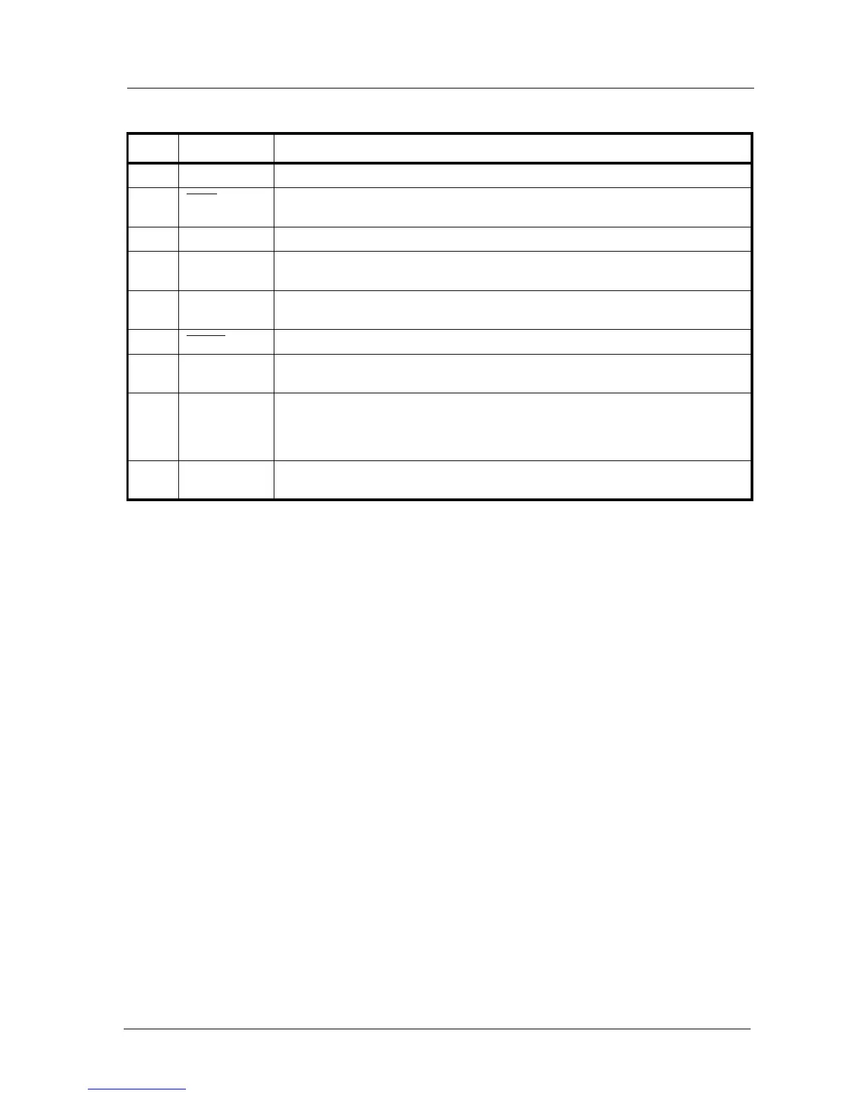
BDI TARGET A Connector Signals
Note:
The BDI actively drives TRST. It does not require any special power-up circuitry. Simply, the require-
ment is that TRST is weakly pulled down at the processor. It is suggested that the value of the pull-
down resistor is 10k or greater.
Pin Name Describtion
1 reserved This pin is currently not used.
2 TRST
JTAG Test Reset
This output of the BDI3000 resets the JTAG TAP controller on the target.
3+5 GND
System Ground
4 TCK
JTAG Test Clock
This output of the BDI3000 connects to the target TCK line.
6 TMS
JTAG Test Mode Select
This output of the BDI3000 connects to the target TMS line.
7 RESET
This open collector output of the BDI3000 is used to reset the target system.
8 TDI
JTAG Test Data In
This output of the BDI3000 connects to the target TDI line.
9 Vcc Target
1.2– 5.0V:
This is the target reference voltage. It indicates that the target has power and it is also used
to create the logic-level reference for the input comparators. It also controls the output logic
levels to the target. It is normally connected to Vdd I/O on the target board.
10 TDO
JTAG Test Data Out
This input to the BDI3000 connects to the target TDO line.