DALI potentiometer for broadcast
operation
Installation and electrical
connection
| 1473-1-7978 — 11 —
Pos: 30 /#Neustruktur#/Modul-Struktur/Online-Dokumentation/Überschriften (--> Für alle Dokumente <--)/2. Ebene/M - O/Montage @ 18\mod_1302615960 458_15.docx @ 103424 @ 2 @ 1
7.2 Mounting
Pos: 31 /#Neustruktur #/Online-Dokumen tation/Sicherhei tshinweise und Hinweis e (--> Für alle Dokumente <--)/Warnhinweise/Sicherheit - 230 V @ 18\mod_1302606816750_1 5.docx @ 103308 @ @ 1
Warnin
Electric voltage!
Risk of death and fire due to electrical voltage of 230 V.
– Work on the 230V supply system may only be performed by authorised electricians!
– Disconnect the mains power supply prior to installation and/or disassembly!
Pos: 32 /#Neustruktur #/Modul-Struktur /Online-Dokumenta tion/Montage/al le Geräte/Montage - UP-Dose n - DIN 49073-1 @ 21\mod_13312 10080219_15.doc x @ 202029 @ @ 1
The device must only be installed in suitable flush-mounted sockets (DIN 49073-1).
Pos: 33 /#Neustruktur #/Modul-Struktur /Online-Dokumenta tion/Montage/Di mmer/Montage - 2117 @ 21\mod_1331 210177831_15.doc x @ 202044 @ 2 @ 1
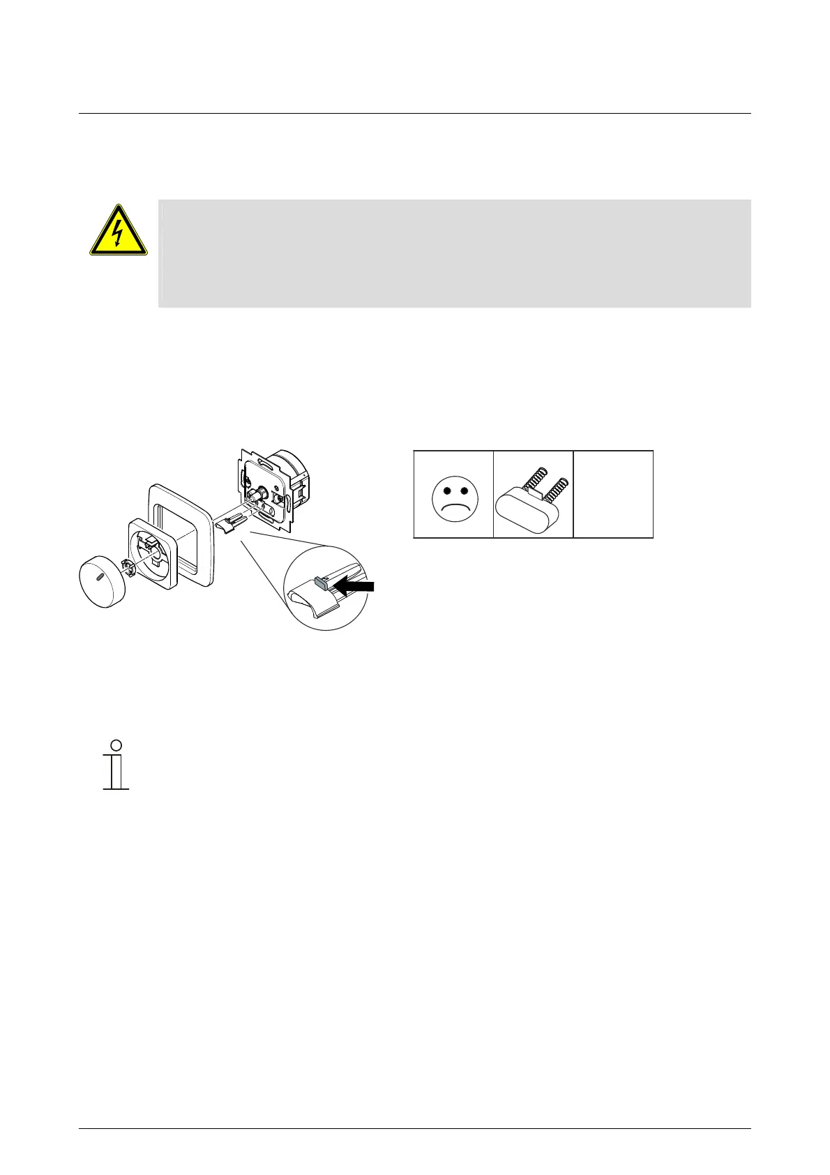
7.3 Inserting optical fibres
Fig. 9:
Insert the optical fibre directly into the two middle openings between the connecting terminals. In the process,
align the plastic lug in the direction of the potentiometer axis.
Hint
• The glow lamps included with the control elements must not be used.
• The control elements of the impuls series are not suitable for illumination!
Pos: 34 /#Neustruktur#/Modul-Struktur/Online-Dokumentation/Steuermodule - Online-Dokumentation (--> Für alle Dokumente <--)/++++++++++++ Seitenumbruc h ++++++++++++ @ 9\mod_1268 898668093_0.docx @ 52149 @ @ 1
! top
3855
3856
Art.