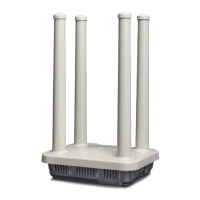
Pin allocation serial interface RS-232 (RJ-12)
RS-232 RS-232 PC SUB-D9
Pin SignalDirection Pin SignalDirection
1 DCD Output 1 DCD Input
2 CTS Output 8 CTS Input
3 RTS Input 7 RTS Output
4 GND - 5 GND -
5 RxD Output 2 RxD Input
6
1
6 TxD Input 3 TxD Output
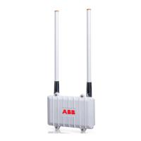
Pin allocation serial interface RS-485 half duplex
(RJ-12)
RS-485 half duplex / 2-wire
Pin Signal Direction
1
2
3 B (-) bi-directional
4 GND -
5
6
1
6 A (+) bi-directional
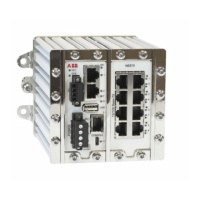
Pin allocation serial interface RS-485 full duplex
(RJ-12)
RS-485 full duplex / 4-wire
Pin Signal Direction
1
2 B (-) Input
3 B (-) Output
4 GND -
5 A (+) Input
6
1
6 A (+) Output
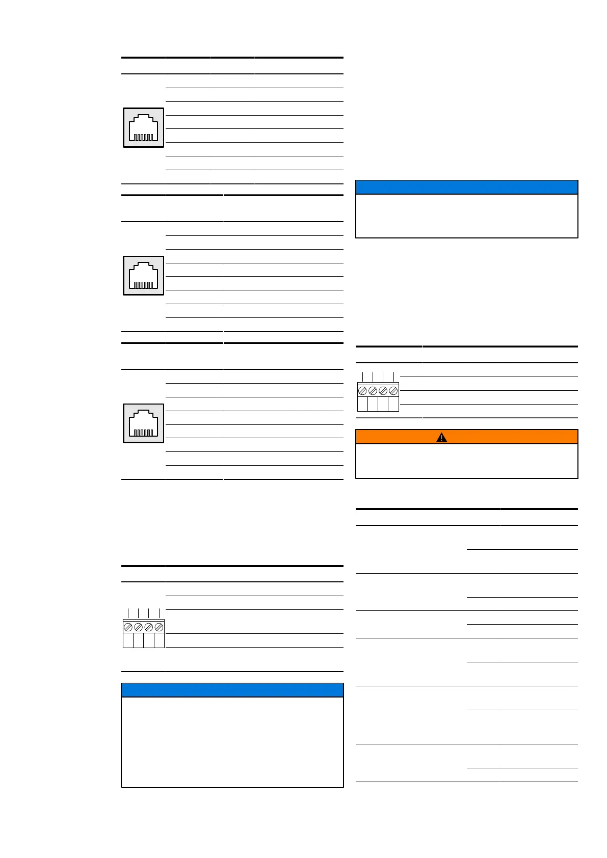
Power connector (X1)
The EDS500 devices are equipped with a wide range
power supply for voltages between 24 and 60 Volts DC
(power consumption see device label). The connector
is a 4-pin Phoenix plug with screw terminals.
Pin allocation power supply (X1)
Pin Signal
1 24-60 V DC
2 Functional earth (internally wired to
pin 4)
3 GND
1 2 3 4
4 Functional earth (internally wired to
pin 2)
ADVICE
Due to the internal overvoltage protection,
interrupt any connection to ground of the device
for the time of the measurement before you carry
out isolation measurement. This includes the
earthing of the hat rail as well as all shields of all
transmission lines and supply feedings. RJ-12 plugs
or RJ-45 plugs can establish earthing via the shield.
Extension interface (EXT)
The plug of the proprietary expansion bus is designed
as USB type B but uses a manufacturer specific
protocol.
The configuration parameters are stored directly
on the device. In addition, a configuration stick can
be connected to the expansion bus to save data
externally, in example to exchange defective devices
easily.
ADVICE
Danger of damaging the device
Do not connect any USB devices!
Alarm-Relay (X2)
The devices are equiped with a potential free alarm
output (relay with isolated switchover contact). This
output corresponds to a device alarm and is activated
when the device looses the power supply or the alarm
LED is constantly on. The reason for the signalling of
an alarm can be referenced in the system alarm table.
Pin allocation alarm output (X2)
Pin Signal
1 & 2 Normal state
1 & 3 Alarm state
1 2 3 4
4 Common contact (connected to 1)
WARNING
The relay is designed for switching only safe low
voltages.
Signaling
LED Description Function
off Device is without
power supply
Power Voltage
Supply
green Power supply
switched on
off Hardware fault or
booting
Ready Ready
green Device ready
off SFP not pluggedFo Module SFP Module
green SFP plugged
off no optical link
active
Fo Link SFP link
green Optical link estab-
lished
off No activity on the
optical interface
Fo Activity SFP activity
green Data is trans-
mitted via the
optical interface
off DCD inactive on
Con interface
Con DCD Con DCD
green DCD active
 Loading...