Operation Manual / 4 Product description / A200-L
9 Taking a turbocharger out of operation / 9.2 Taking defective tur-
bochargers out of operation
© Copyright 2018 ABB. All rights reserved. HZTL4036_EN Revision N November 2018
9.2.5 Engines without bypass around the turbocharger
To obtain a higher engine performance, the nozzle ring can be removed if required (see
chapter Disassembly and assembly →50).
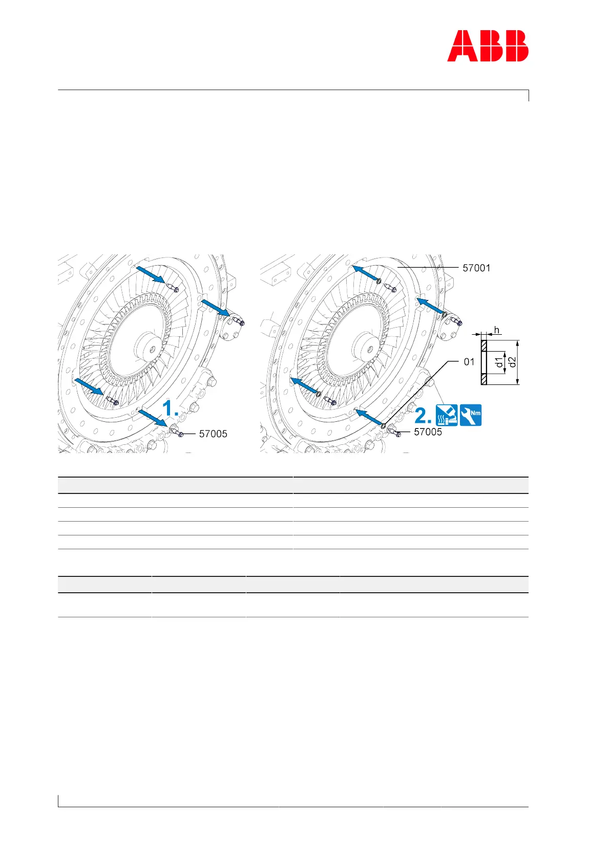
Securing the cover ring
If the nozzle ring is removed for emergency operation, the clamping of the cover ring(57001)
to the gas outlet casing must be ensured. In this case, additional washers(01) must be
provided in accordance with the following table. These washers(01) are not supplied by ABB.
Fig.63: Ensuring clamping of the cover ring
Product h [mm] d1 [mm] d2 [mm]
A265-L 3.5 … 4.0 13 20
A270-L 3.5 … 4.0 13 20
A275-L 4.0 … 5.0 17 28
A280-L 4.0 … 5.0 21 34
Table48: Required washers (01)
Part number A265-L A270-L A275-L A280-L
57005 M12
50Nm
M12
50Nm
M16
80Nm
M20
160Nm
Table49: Tightening torque (57005)
1. Remove screws(57005).
2. Fit and tighten screws(57005) with high-temperature grease and washers(01) in accord-
ance with the table.
9.2.6 Blanking off the inlets and outlets
The chapter is only applicable for engines with several turbochargers and joint air and ex-
haust gas receivers. The cover plates for the compressor casing outlet, gas inlet and gas
outlet are not included in the ABB scope of delivery.
The following figure shows the positions where to fit the cover plates.
Page 94 / 108