Electrical installation
88
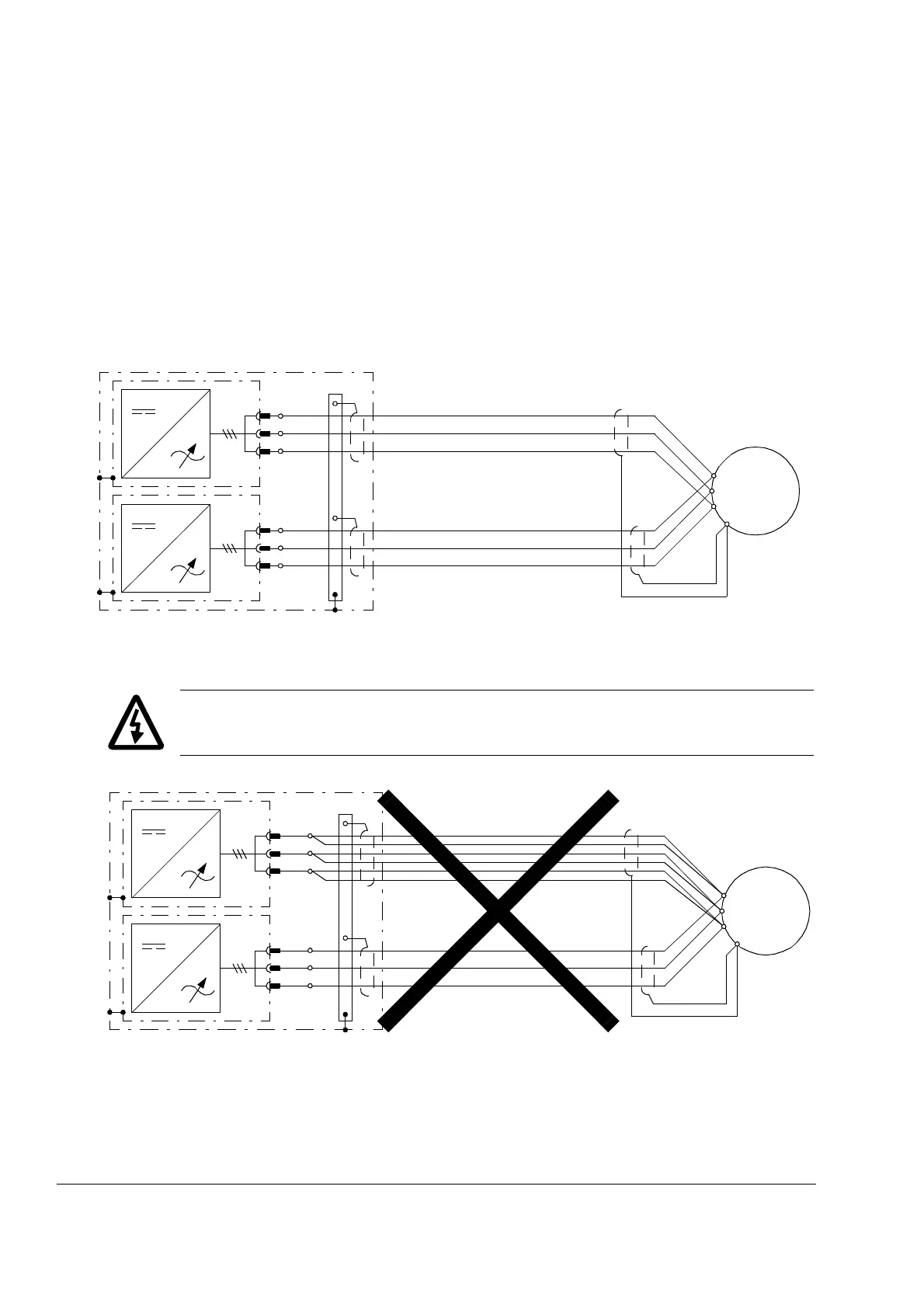
Motor connection – Frame 2×R8i and up without common motor terminal
cubicle
Output busbars
The motor cables are to be connected to the output busbars behind each inverter
module. For the location and dimensions of the busbars, see the chapter
Dimensions.
Connection diagram
WARNING! The cabling from all inverter modules to the motor must be physically
identical considering cable type, cross-sectional area, and length.
U2
V2
W2
PE
U2
V2
W2
M
3~
U1
W1
V1
PE
Inverter unit cubicle(s)
PE
Inverter unit cubicle
U2
V2
W2
U2
V2
W2
M
3~
U1
W1
V1
PE
 Loading...


