D1073S relays by default. PRelectronics 9116B1 relays are available as application
engineered.
1-2 Current output
• 1: + Output channel 1 for Current Source Mode or Voltage
Source Mode*
• 2: - Output channel 1 for Current Source Mode or Voltage
Source Mode*
This output has been pre-wired to terminal block X506. See
the circuit diagrams starting on page 71.
3-4 Power supply
• 3: + 24 V DC
• 4: - 24 V DC
5-6 Output contacts (Alarm A)
7-8 Output contacts (Alarm B)
13-16 Measuring circuit
• 13: Input channel 1 for 3-4 wire RTD, Reference Junction
Compensator Option 91 or potentiometer*
• 14: Input channel 1 for 3-4 wire RTD
• 15: + Input channel 1 for 4 wire RTD, thermocouple TC or
potentiometer*
• 16: Input channel 1 for 3-4 wire RTD, thermocouple TC or
potentiometer*
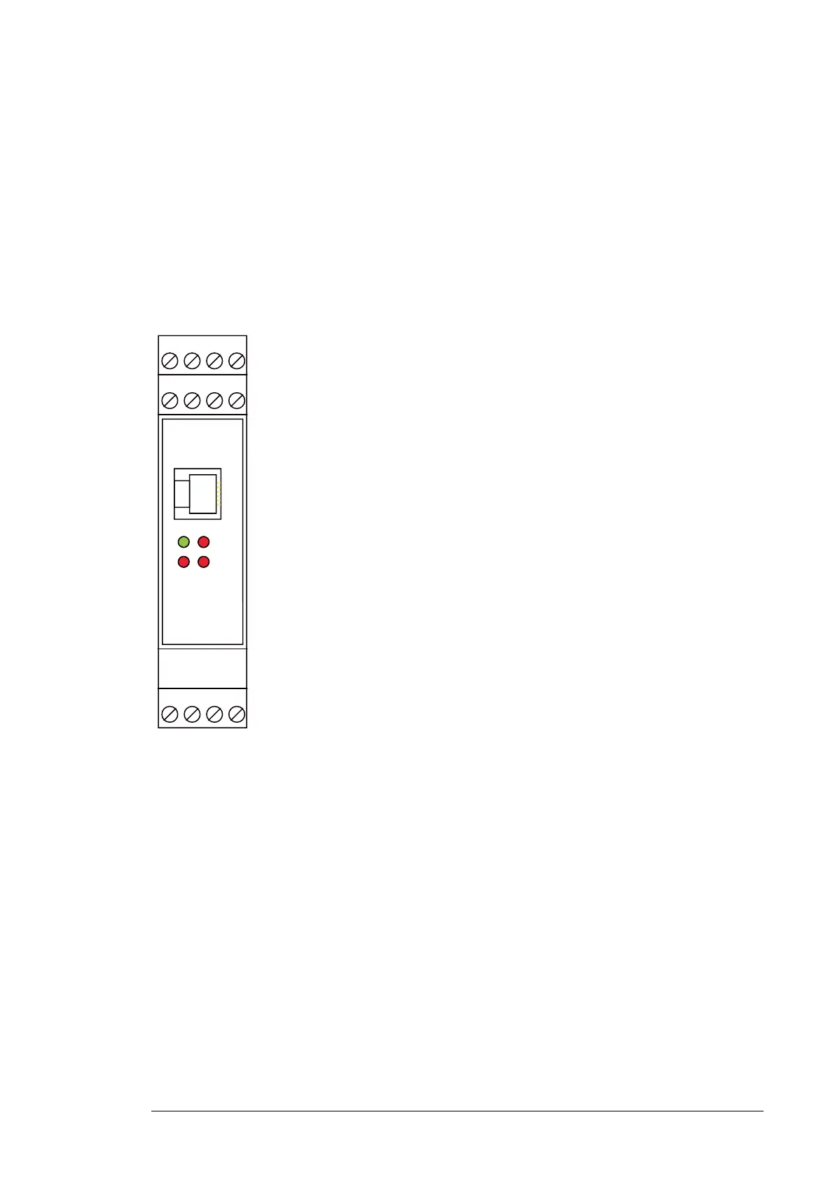
CONF Programming channel
“PWR” LED (green) Supply voltage present
“BURN” LED (red) Burnout detected
“A” LED (red) Alarm A**
“B” LED (red) Alarm B**
*Voltage Source Mode, Reference Junction Compensator Option 91, potentiometer
and thermocouple TC are not used in the particular application described by this
manual.
**Note: For SIL applications, alarm contacts must be used in series with equal
configuration. Relay contact shown in de-energized position.

 Loading...