20
ABB
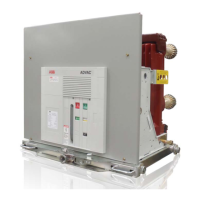
To verify the integrity of the primary insulation, perform the following low-frequency withstand voltage test:
1. Close the breaker (no control power supplied to breaker)
a. Connect the high potential lead to one pole
b. Ground the remaining poles and breaker frame
2. Start machine with output potential at 0 (zero) VAC.
3. Increase the potential to the required voltage (see Table 2)
4. Hold for one minute
5. Decrease potential to 0 (zero) VAC and turn off machine
6. Repeat for the remaining poles
A successful withstand indicates satisfactory insulation strength
of the primary circuit.
To verify the integrity of the vacuum interrupters perform the following low-frequency withstand voltage test:
1. Open the breaker (no control power supplied to breaker)
a. Connect the high potential lead to one terminal
b. Ground the remaining 5 terminals and breaker frame
2. Start machine with output potential at 0 (zero) VAC
3. Increase the potential to the required voltage (see Table 2)
4. Hold for one minute
5. Decrease potential to 0 (zero) and turn off machine
6. Repeat for the remaining 5 terminals
A successful withstand indicates satisfactory vacuum integrity.
CAUTION
Applying abnormally high voltage across a pair of open contacts in
vacuum may produce X-radiation. The radiation may increase with
the increase in voltage and/or decrease in contact spacing. It is
recommended that all operating personnel stand at least one meter
away and in front of the circuit breaker during testing.
DANGER
The internal shield of a vacuum interrupter can acquire an electric
charge which CAN BE retained even after the voltage is removed.
Discharge the mid-band ring with a grounding stick before
working on any part of the circuit breaker.
MAINTENANCE
Replace interrupters that fail to sustain the voltage across the open contacts.
Testing should be done with an AC source only. DC testing is not considered a valid test for vacuum integrity. If DC
is the only available option, the peak DC voltage should not exceed the corresponding AC RMS test voltage. Addition-
ally, a failure during DC testing should only be considered preliminary. Additional AC testing should be completed be-
fore replacement of the pole is considered to be warranted. Testing with meggers or other similar devices is not con-
sidered valid under any circumstances.
Table 2: Primary Low-Frequency Withstand Test
Voltages
Rated Max
Voltage
Dielectric Test
Value, 1 Minute
Dry AC rms
4.76kV 15kV
8.25kV 27kV
15kV 27kV
Courtesy of NationalSwitchgear.com
 Loading...