21
ABB
G&T DEVICE
G&T D
EVICE
:
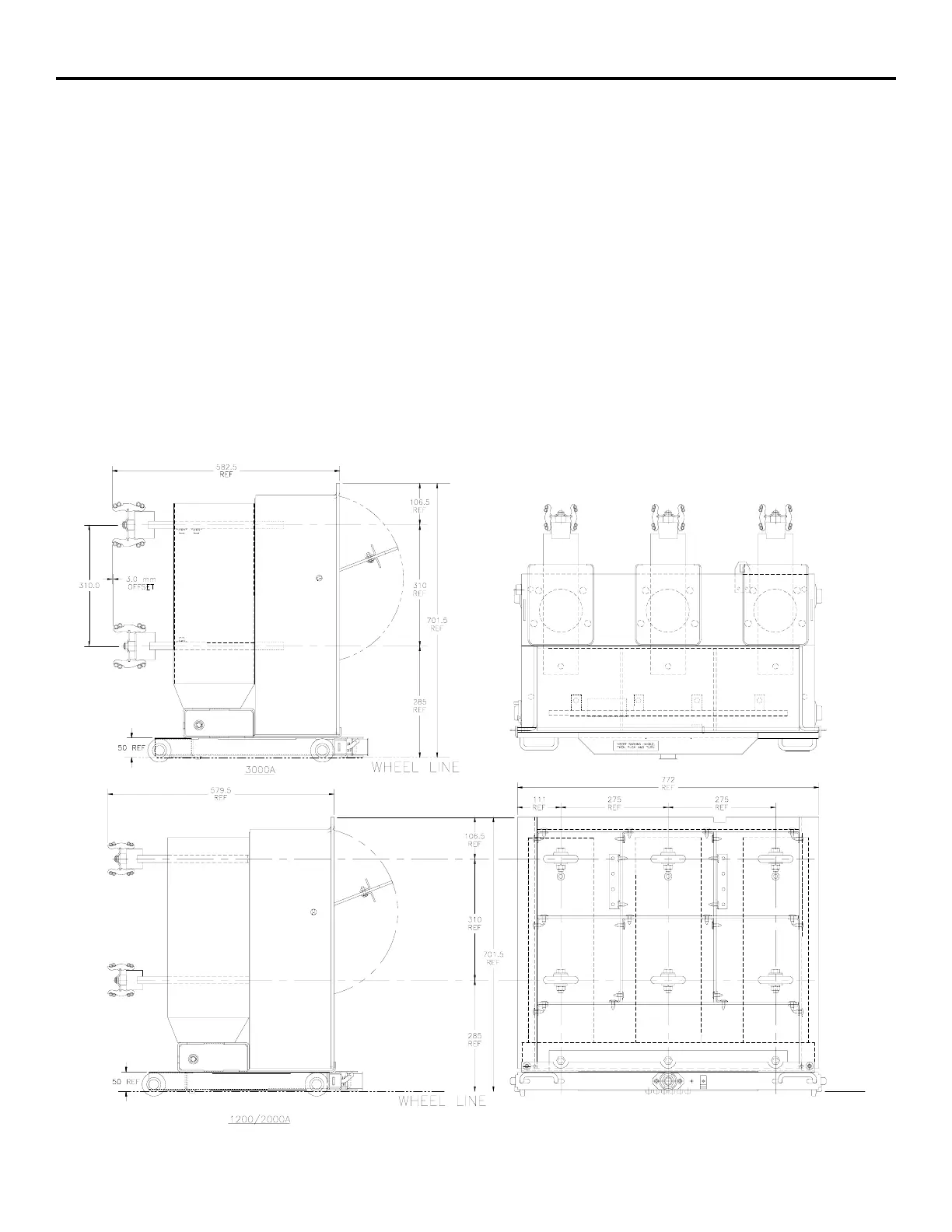
The G&T device is designed for use in grounding and/or testing a circuit. The device is a manual cable device. The
cables are used to provide a solid path to the main ground bus of the switchgear though the automatic ground of the
G&T device. The cables are manually attached to each lead of the upper or lower lead set with the bolts and nuts
provided.
Insertion and racking of the G&T Device is similar to the circuit breaker; however, there are only two positions:
Disconnect and Connect. No position release is required. The automatic ground on the device makes its connection
when the device is inserted into the cell in the Disconnect position. The ground remains in contact throughout the
racking process.
All standard safety practices should be adhered to when using this device. Typical operating instructions are included
on the labels located on the G&T device front panel. A copy of this label is shown on the next page.
Figure 6: G&T Layout
582.5
REF
106.5
REF
Ti
-
er
IS
r
~
i
r
-
©
3.0
mm
OFFSET
310.0
If
.
N
.
K
7
7
<
/
!
\
/
!
\
I
/
:
i
\
i
l
.
5
,
-
f
O
o
'
1
1
/
s
.
A
A
i
/
A
O
O
I
.
)
'
K
i
E
,
i
o
o
o
i
:
o
o
285
Cl
:
REF
u
L
J
1
if
37
I
INSERT
RACK
INC
MANOlE
.
I
THEN
PUSH
AND
TURN
Q
50
REF
l
.
IVi
.
T
"
WHEEL
LINE
3000
A
772
REF
579.5
REF
1
11
275
275
REF REF REF
-
r
-
m
106.5
a
:
REF
A A
±
A
A
A
-
-
o
3
-
-
O
O
©
A
J
o
o
o
<
r
:
o
(
ED
310
F
if
-
REF
701.5
REF
/
i
W W
w
4
%
r
285
r
-
H
j
.
J
.
rin
REF
J
&
HU
.
i i
O
0
fS
Si
i
G
50
REF
+
n
JiL
T
"
WHEEL
LINE
120
Q
/
2000
A
Courtesy of NationalSwitchgear.com
 Loading...