COMMISSIONING AND TESTING GUIDE 23
Breakers installed but no main bus in the
switchgear frame
This testing method includes the influence of
application, such as the circuit breaker or
contactor, which are used to make an electrical
circuit between the cable and busbar
compartments. The above mentioned testing
method is preferred by switchgear factories for
the primary testing of current sensors in a
workshop.
Danger: If high voltage cables are terminated to
switchgear frame, ensure the installation is dead.
Protect against any other live parts.
• Step 1/7
Verify sensor parameters set in the protection
relay with sensor rating plates found on the
sensors. These may be found on the circuit
breaker compartment door or in the low voltage
wiring compartment.
• Step 2/7
Move the circuit breaker into the connected
position and close it.
Notice: Default values of
overcurrent, earth fault and
unbalance protection functions can
operate the circuit breaker during
primary injection. Disable all related
protection functions in the
protection relay or disconnect the
tripping coil (MO) from the negative
potential of power supply in the low
voltage compartment before the
primary injection to avoid un-
wanted tripping of the circuit
breaker.
• Step 3/7
Remove the main bus compartment barrier to
access the jump bus from the top of the
breaker. If Is limiters are installed, make sure
they will not trip your circuit breaker, for
example, by disconnecting them from the
tripping circuit.
• Step 4/7
In the cable compartment, connect the second
end of the primary injection test set to the
cable sealing end and the busbar compartment
to the branch conductor of the same phase. See
the picture below.
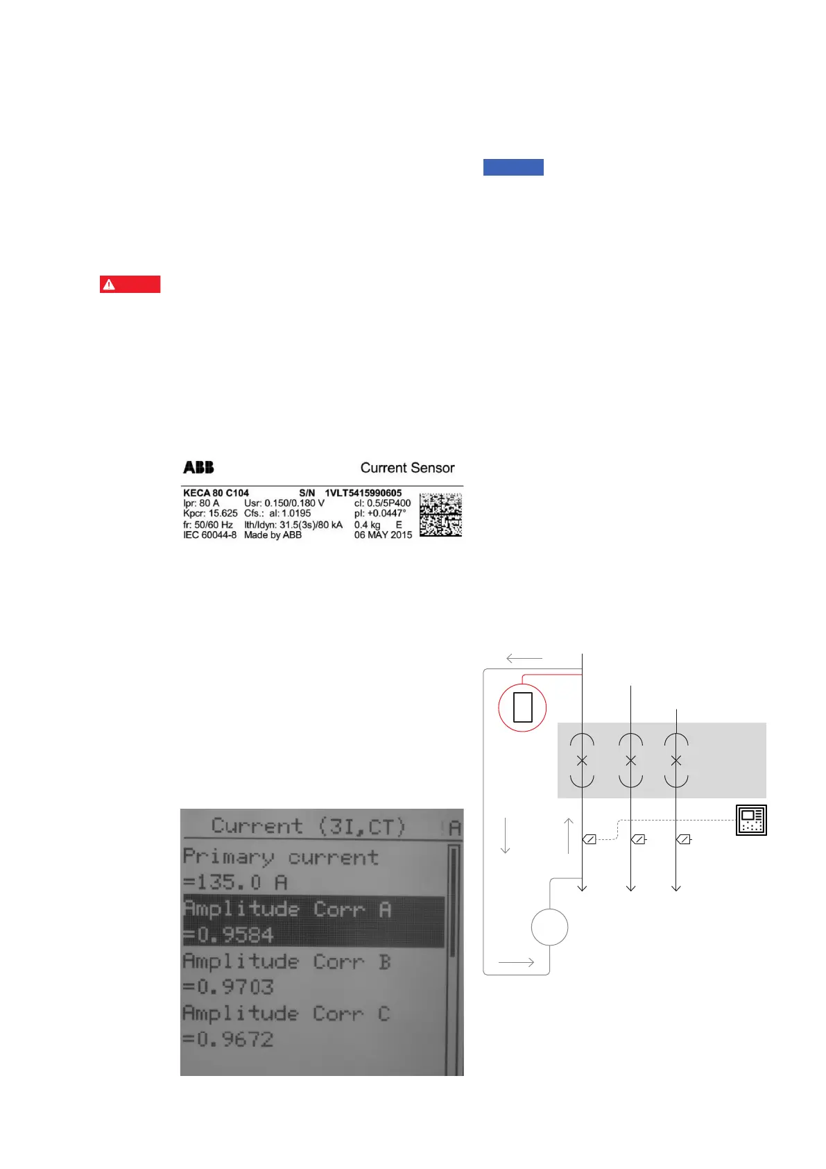
On the protection relay LHMI go to -> Main Menu/
Configuration/Analog inputs/ Current (3I, CT)
• Primary current = Application nominal current
• Amplitude Corr A = sensor rating plate, phase A
• Amplitude Corr B = sensor rating plate, phase B
• Amplitude Corr C = sensor rating plate, phase C
• Nominal current = Primary current
• Rated secondary Val = Rated secondary value in
mV/Hz
• Angle Corr A = sensor rating plate phase A
• Angle Corr B = sensor rating plate phase B
• Angle Corr C = sensor rating plate, phase C
—
36
—
37
—
38
—
36 Example of a
current sensor label
—
37 Current sensor
parameters
—
38 Test setup for current
sensors when busbars
are not installed
DANGER
WARNING
CAUTION
NOTICE
SAFETY
INSTRUCTIONS
L1
L1
L2
L3
Circuit
breaker
0V 0V 0V
II
Primary
tester
~I (A)
I
I