COMMISSIONING AND TESTING GUIDE 27
• Step 2/7
Warning: Ensure that all equipment is de-
energized and all safety interlocks and/or lock-
out-tag-out procedures are followed to ensure
equipment is safe to work on in primary
compartments.
• Step 3/7
Isolate tested phases. Remove the circuit
breaker out of the switchgear frame. Any high
voltage cables terminated at the frame should
be disconnected for safety reasons.
• Step 4/7
Except the tested phase, connect all other
phases together to the grounding bar.
• Step 5/7
Connect the primary tester to the cable
connection end of the isolated phase and to the
ground bus inside the switchgear frame. (Note:
ground bus connection can be made in breaker
or cable compartment.)
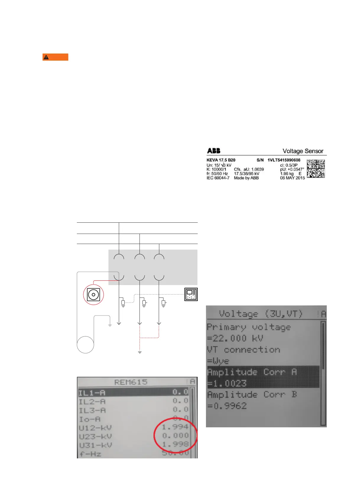
Since the protection relay is reporting phase-to-
phase voltages, two identical measurements will
appear on the display. For example, if voltage is
applied between phase 1 and the ground, then
Voltage sensor installed on main bus
• Step 1/8
Verify sensor parameters set in the protection
relay with sensor rating plates found on the
sensors. These may be found on the circuit
breaker compartment door or in the low voltage
wiring compartment.
WARNING
—
42 Test setup for voltage
sensors installed in the
cable compartment
—
43 Measurements
view, injected phase 1
—
44 Example of a
voltage sensor label
—
45 Voltage sensor
parameters
—
43
—
42
—
45
—
44
On the protection relay LHMI go to -> Main Menu/
Configuration/Analog inputs/Voltage (3U, VT)
• Primary voltage = Nominal voltage of the
network
• VT connection = Wye (star connection)
• Amplitude Corr A = sensor rating plate, phase A
• Amplitude Corr B = sensor rating plate, phase B
• Amplitude Corr C = sensor rating plate, phase C
• Division ration = 10 000
• Voltage input type = RVD sensor
• Angle Corr A = sensor rating plate phase A
• Angle Corr B = sensor rating plate phase B
• Angle Corr C = sensor rating plate, phase C
L1
L2
L3
No
circuit
breaker
U
0V 0V
Primary
tester
~U (V)