30 ANSI MEDIUM VOLTAGE METAL-CLAD DIGITAL SWITCHGEAR
• Step 1/10
Move all circuit breakers into the service
position in the relative section. Check all the
circuit breakers status on the protection relay
LHMIs.
IA=0A
IB=0A
IC=0A
IG=0.0A
VAB=0.00kV
VBC=0.00kV
VCA=0.00kV
3P=0kW
3Q=0kVAr
—
54
• Step 2/10
Close the circuit breaker in the feeder to be
tested. Check the circuit breaker status on the
protection relay LHMI.
IA=0A
IB=0A
IC=0A
IG=0.0A
VAB=0.00kV
VBC=0.00kV
VCA=0.00kV
3P=0kW
3Q=0kVAr
—
55
• Step 3/10
Close all upstream breakers in the relative
section, such as the Incomer, Generator and Bus
tie.
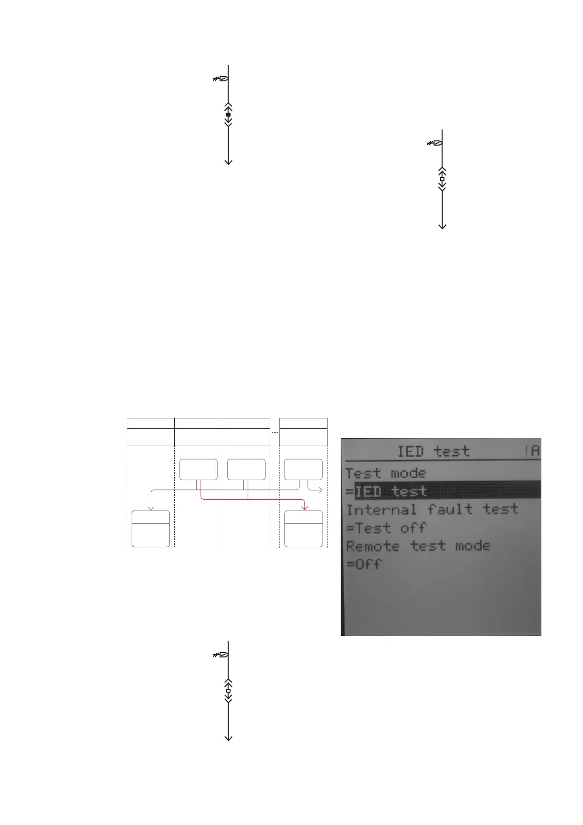
• Step 4/10
On the protection relay LHMI (upstream breaker
receiving CBFP trip command) go to -> Main
Menu/Test/IED test
- Test mode = IED test
The ready LED is flashing when the protection
relay is in the test mode.
—
56
IA (0)A
IB (0)A
IC (0)A
IG (0.0)A
VAB (0.0)kV
VBC (0.0)kV
VCA (0.0)kV
3P=(0)kW
3Q=(0)kVAr
• Step 7/ 7
Check the impossibility of isolating the circuit
breaker from service when it is closed.
Circuit breaker failure protection (CBFP)
When included in the protection and control
schemes, the protection relay supervise trip
command is processed by the Circuit breaker in
the expected “tripping” time. For medium voltage
the application usually uses a time delay of 300
ms. In case of a delay, the protection relay sends
the tripping command to the upstream circuit
breaker, typically to the In-comer and Bus tie.
It is good practice to block the CCBRBRF function
if the circuit breaker is in the test or a
disconnected position.
—
52 Single line diagram,
the circuit breaker
is closed and in the
service position
—
53 Logic scheme of CBFP
—
54 Single line diagram,
the circuit breaker in
the service position
—
53 Single line diagram
circuit, the circuit
breaker is closed and
in the service position
—
56 Entering test mode
—
52
—
53
A01
Incoming feeder Motor feeder
Transformer
feeder
Bus tie
CBFP trip
OR OR
Trip from
external CBFP
Trip from
external CBFP
CBFP trip CBFP trip
A02 A03 AB1 2 3 10