36 ANSI MEDIUM VOLTAGE METAL-CLAD DIGITAL SWITCHGEAR
• Step 1/3
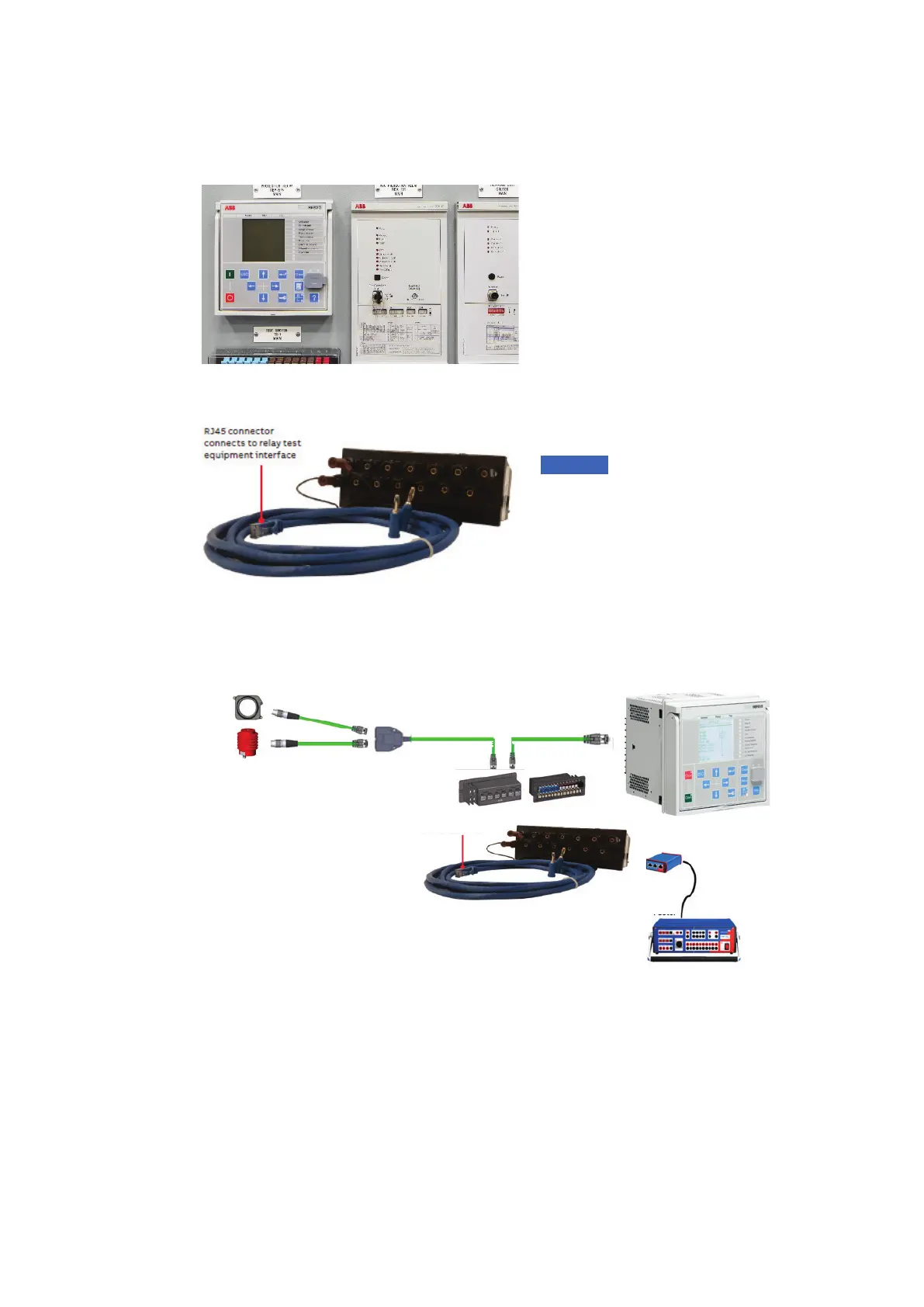
Connect the FT-14D test harness RJ45
connectors to an interface adapter that is
plugged into the protection relay test
equipment.
• Step 2/3
Insert the banana plugs into the FT-14 separate
source test plug.
• Step 3/3
Insert the FT-14 separate source test plug into
the FT-14D by placing the switch blades in open
position. This procedure disconnects the low-
energy current and voltage sensors from the
relay and allows testing to be performed with
the relay test equipment.
The switch blades are closed during normal
operation. For testing, the switch blades are
opened to access the switch jaw.
—
72 Low Voltage
Compartment door of
SafeGear with FT-14D
digital flexitest switch
—
73 FT-14 separate
source test plug
and test harness
—
74 The testing (only one
phase testing setup is
shown in the picture)
—
72
—
73
—
74
Notice: Due to the low-energy
sensing during system operation, it
is important not to touch the open
or closed FT-14D switch jaw
terminals since relay misoperation
can occur. Therefore, during
testing and maintenance, it is also
recommended the relay trip circuit
be disconnected first as a
precaution.
Sensors
Test switch Protection relay
L1 L1
FT-14D digital test switch
(one per 3 phases)
Tester
Test set with adapter
RJ45 connector
connects to relay test
equipment interface