40 ANSI MEDIUM VOLTAGE METAL-CLAD DIGITAL SWITCHGEAR
—
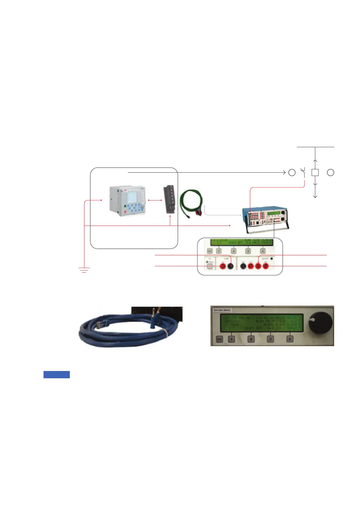
83 1 phase test setup
for the Megger tester
—
84 Connecting cable
with RJ45 connector
and banana contacts
—
85 Setting of high
voltage analog outputs
on the Freja 300 HMI
Test Setup for Megger – 1 phase
For high setting of overcurrent protection, you
may need to apply at max. 93.75 Vrms, 50 Hz
which represent 50 kA symmetrical short circuit
current on the primary side. Therefore, it is
recommended to use high voltage outputs
situated on the front side. These can be
connected to the protection relay as a 1 phase
tester.
• Step 1/3
The protection relay and tester must be
grounded on the same potential.
—
84
—
85
• Step 2/3
Megger tester is connected via connecting
cable terminated with banana connectors and
RJ45 connector on the other one end to the
ESSAILEC® test block or directly to the
protection relay if the ESSAILEC® test block is
not installed. Wires for the voltage sensor are
connected to the Uref output as Phase – Earth
voltage. Wires for the current sensor are
connected to the UL1, UL2 voltage output.
Notice: Figure 84: Connecting cable with RJ45
connector and banana contacts can be ordered
separately if needed.
• Step 3/3
Simulate high currents on the current sensor
input via the front voltage outputs L1U, L2U.
- U1 = U2 with 180° phase shift (symmetrical
source)
Simulate voltage on the voltage sensor input via
the front voltage output U4, NU.
•
—
83
Circuit breaker
open, auxiliary
NO contact
Connecting
sensor cable
with banana
connectors
Voltage sensor signal
PIN 7, 8
Current sensor signal
PIN 4, 5
Simulated current
up to 50 kA
86MO
FT-14 D
test switch
Low voltage compartment of
switchgear panel
Tripping contact
Trip command
Stop timer