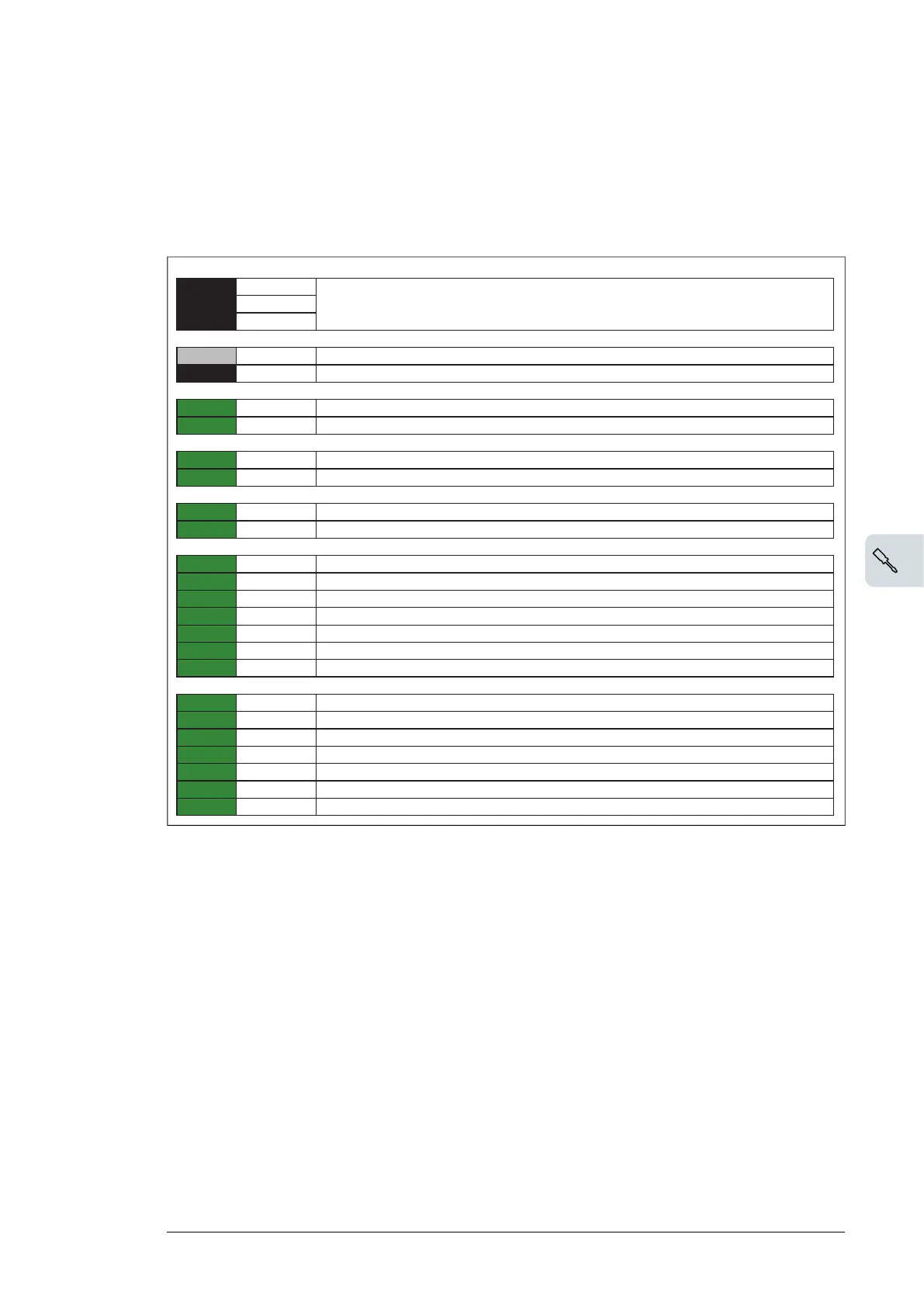
Electrical installation
■ Connection diagram
Default use of the connectors is shown below. For further details on wiring, see the
delivery-specific circuit diagrams.
XPOW External power input
1 24V
24 V DC
2 0V
3 SHIELD
V30 Fiber optic connections
V1T V1T Fiber optic connector, transmitter. Connected to the control unit of the drive.
V1R V1R Fiber optic connector, receiver. Connected to the control unit of the drive.
XIU Current measurement
1)
1 S1 U-phase current input
2 S2
U-phase current output
XIV Current measurement
1)
3 S3 V-phase current input
4 S4
V-phase current output
XIW Current measurement
1)
5 S5 W-phase current input
6 S6
W-phase current output
XU1 Voltage measurement
2)
1 U1 U-phase voltage 1
2 -
Not connected
3 V1 V-phase voltage 1
4 -
Not connected
5 W1 W-phase voltage 1
6 -
Not connected
7 N1 Neutral 1
XU2 Voltage measurement
2)
1 U2 U-phase voltage 2
2 -
Not connected
3 V2 V-phase voltage 2
4 -
Not connected
5 W2 W-phase voltage 2
6 -
Not connected
7 N2 Neutral 2
1)
Measuring range: ±2.5 A. Input impedance: <0.2 ohm
2)
Measuring range: ±2.0 kV peak (phase-to-phase), 1250 V rms (phase-to-phase). Maximum
voltage connected to terminals is 600/690 V (DVC C). Input impedance against virtual
ground: 1.76 Mohm.
Installation 17