2-8MN1240
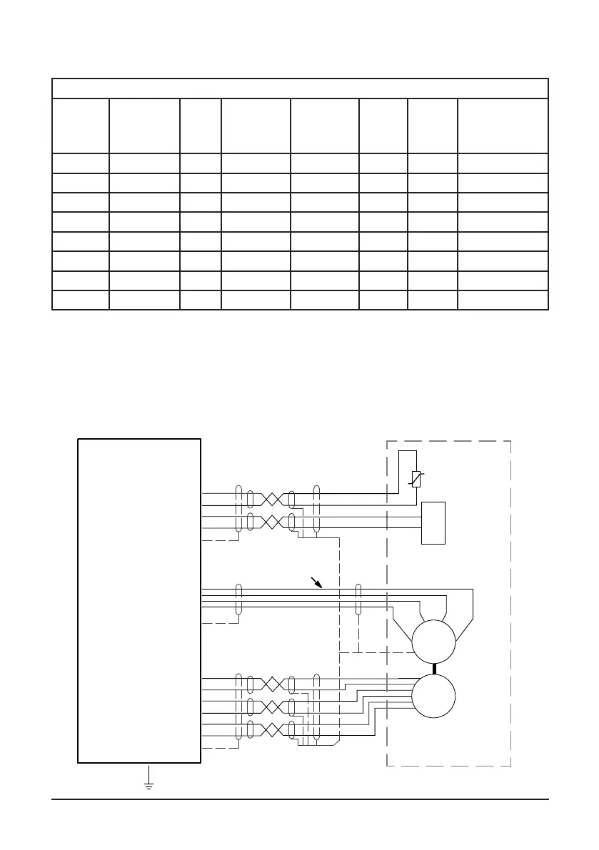
Table 2-1 Brake Specifications
Brake data for BSM and SSBSM
Motor
Code
Brake
Holding
Torque Nm
(lb-in)
Watts Brake
voltage
(Vdc)
Brake
current
(amps)
Set
Time
(ms)
Release
Time
(ms)
Brake inertia
Kg-cm²
(lb-in-s²)
BSM50N 1.1 (10) 12.4 24 0.52 3 20 0.019 (0.000017)
BSM63N 2 (18) 17 24 0.71 16 43 0.018 (0.000016)
BSM80 4.5 (40) 17 24 0.71 9 48 0.125 (0.000111)
BSM90 15.8 (140) 22 24 0.92 14 110 0.181 (0.00016)
BSM100 39.5 (350) 19 24 0.79 22 195 0.723 (0.00064)
BSM25C 1.7 (15) 9.6 24 0.4 16 27 0.034 (0.00003)
BSM33C 15.8 (140) 21.6 24 0.9 14 110 0.181 (0.00016)
BSM132C 101.7 (900) 76 24 3.17 129 163 17.277 (0.01529)
Note: All standard brakes used on BSM motors are 24 Vdc. The application needs to provide this voltage to release
the brake. The brake is a safety brake only and not intended to be used to decelerate loads. Contact ABB for details.
Detailed engineering drawings are available upon request.
Electrical Connections
Overview Figure 2-7 shows typical connections to a control. Note all wiring should be
600volts.
Figure 2-7 Typical Connections to Motor Control
AC MotorU
V W
G
Control
Feedback
Motor
Holding
Brake
Motor
Temperature
Switch
Shielded
Twisted Pair Wire
Shielded
Twisted Pair Wire
Feedback
Connector
Motor
Connector
Motor Ground Wire
Motor Temperature Input
Holding Brake Connector
Single Point Ground
Shielded Motor Cable
All wiring should have 600V rated insulation.