2-9 MN1240
Motor Lead Termination
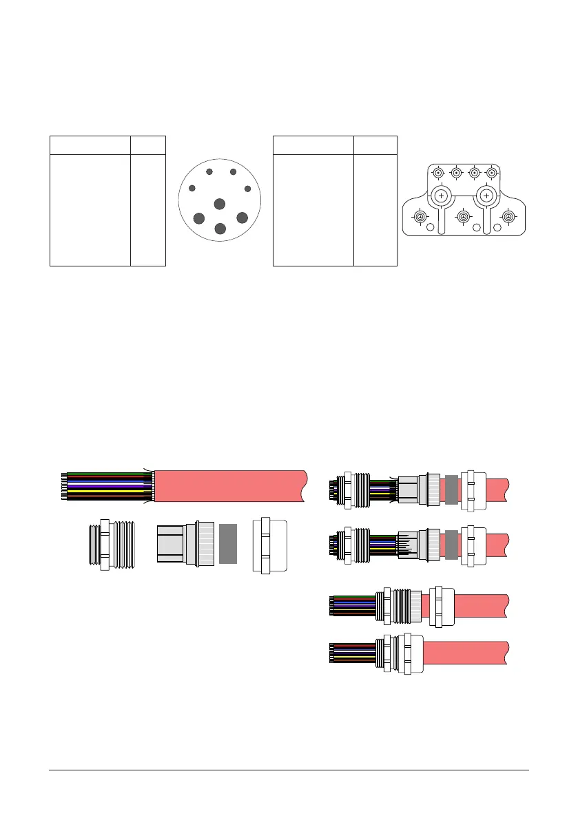
Motor leads are normally terminated using a Connector or Terminal Box (see Figure
2-8) or Flying Leads. When no termination is provided and the motor leads just exit
the motor housing, this is called “Flying Leads”. For ying leads, refer to the motor
packing list to determine the lead conguration.
Figure 2-8 Motor Termination
Function Pin 8 Pin Function Pin
1 2
U
V
W
3 4
Thermal Switch
Thermal Switch
Brake
Brake
U
Ground
W
V
A
B
C
D
1
2
3
4
1
D
2
3
4
C
B
A
Thermal Switch
Thermal Switch
Brake
Brake
U
W
V
Ground (P.E.)
1
2
3
4
U
V
W
Screw
Connector Termination Terminal Box Termination
Strain Relief (Mounted at Terminal Box)
The motor cable is terminated at the Terminal Box using a Shielded Strain Relief Connector.
Figure 2-9 shows the components.
1. Strip the outer shield from the cable to expose the conductors and shield.
2. Slip the Strain Relief components onto the cable in the order shown.
3. Fold the Shield wires over the end of the Contact Carrier.
4. Slide the Threaded Adapter onto the Contact Carrier until the Carrier is
completely inserted into the Adapter.
5. Slide the Gasket into the Contact Carrier.
6. Slide the Adapter Cover onto the Threaded Adapter and Tighten. As it is
tightened, it compresses the Gasket against the Cable to form the strain
relief and securely hold the cable.
7. The assembly can be inserted into the Terminal Box and secured.
Figure 2-9 Motor Cable Strain Relief Assembly
Threaded
Adapter
Gasket Adapter
Cover
Contact
Carrier
Shielded Cable
Assemble Parts onto Cable
Assembled
Fold Shield wires over Contact Carrier
Feedback Termination
Connections for Feedback cables are different for each type of feedback device.
Standard devices are: Resolver, Halls (Hall Effect), Incremental Encoder with Halls,
and Absolute Encoders including SSI, EnDat, BiSS, and Hiperface.
Custom feedback devices are also available. Request a drawing of your feedback
device to determine the pin−out and/or wire color codes.