24
1ZSE 5492-128 en, Rev. 4
1
3
5
7
9
11
13
15
17
fm_00108
fm_00108
3.4.3 Material and spare parts required
Each end stop consists of:
■ One socket head cap screw M5x12
■ One lock nut M5
3.4.4 Procedure
1. Change the lower end stop in the following way:
- Operate to the new lowest position +1.
- Mark up the rst hole below the pivoting arm (Fig. 9).
- Operate the on-load tap-changer to a position where the marked hole is accessible
and mount the extra stop screw.
3 Repairs and adjustments
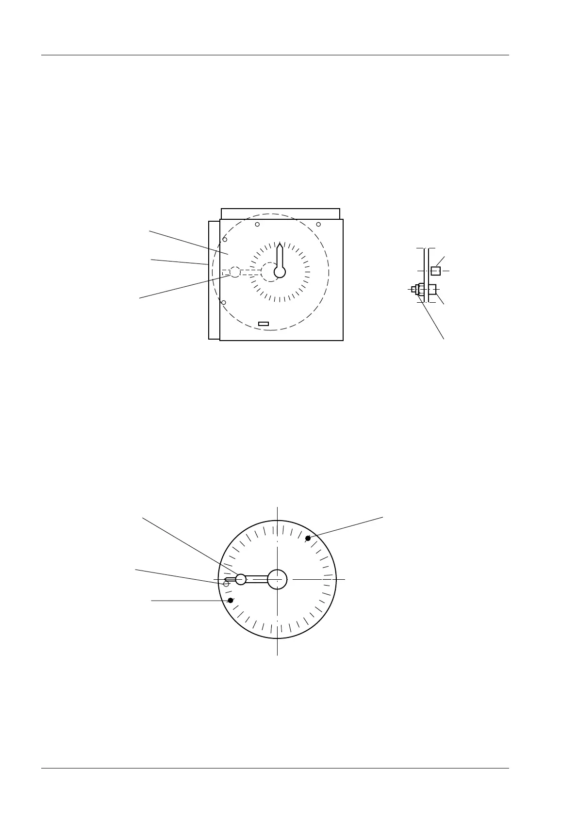
Lock nut M5
Socket head cap
screw M5x12
Pivoting arm
Indicating plate
Protection plate
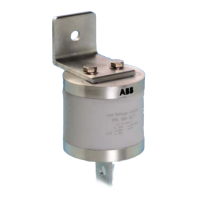
Pivoting arm
Fig. 9.
Pivoting arm
Stop screw
Lower end stop
Upper end stop
Fig. 8.